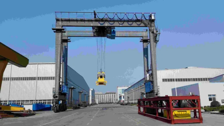
MU Shipbuilding Gantry Crane
For shipyards that need a rail-mounted gantry crane for ship block lifting, turning and final assembly, with project-specific single- or double-girder structure and rigid/flexible leg support.

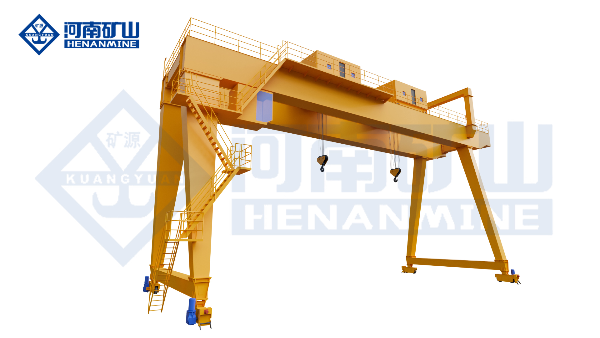
Henan Mine Crane MU shipbuilding gantry crane source image associated with shipyard block lifting, turning and assembly operations.
The MU shipbuilding gantry crane is a bridge-type crane installed on dock or slipway rails. The source states that the crane uses a portal frame with either double main girders or a single main girder and is supported by a combination of rigid and flexible legs.
Its core shipbuilding duties are lifting hull sections, turning ship blocks and completing block assembly. For procurement, the crane should therefore be selected from the actual ship-block weight, dimensions, center of gravity, lifting points, turning method, assembly tolerances, rail gauge, lifting height and shipyard wind environment rather than from crane tonnage alone.
Quick Specifications
| Product Model |
MU |
| Type-Test Product Name |
Shipbuilding Gantry Crane |
| Primary Application |
Ship block lifting, turning and assembly |
| Main Girder |
Single or double main girder according to source / project |
| Leg Arrangement |
Rigid leg + flexible leg combination |
| Travel System |
Rail-mounted on dock or slipway |
| Control |
PLC + inverter communication control (source-confirmed) |
| Safety Monitoring |
Complete-crane safety monitoring system (source-confirmed) |
| Rated Capacity |
Configured according to ship-block load and lifting arrangement |
| Span / Rail Gauge |
Configured according to dock / slipway rail layout |
| Lifting Height |
Configured according to block turning and assembly envelope |
| Working Duty |
Configured according to shipyard production cycle |
Best For: Shipyards, docks and slipways where large hull sections must be lifted, turned, aligned and assembled within a fixed rail-served production area.
Request A MU Shipbuilding Gantry Crane Quote
Product Overview
The source defines the MU crane as a special shipbuilding gantry installed on shipyard rails. Its portal frame can use a single- or double-main-girder structure and is supported by rigid and flexible legs to accommodate the large-span gantry arrangement.
Unlike a general yard gantry crane, the purchasing decision is driven by hull-section handling. The crane must cover the full block envelope during pickup, travel, turning and final fit-up. The shipyard should provide the largest block, heaviest block, lifting-lug positions, center of gravity and the exact turning / erection sequence before detailed design.
The source does not publish one universal capacity, span, lifting height, travel speed, turning synchronization tolerance, wind limit or positioning accuracy. These values should be engineered from the actual shipyard process and written into the technical agreement.
Why Choose a Shipbuilding Gantry Crane?
Designed Around Ship Blocks
The source specifically identifies hull-section lifting, turning and assembly as the core operating tasks.
Rigid + Flexible Leg Support
This source-confirmed arrangement is appropriate for a large rail-mounted portal frame and helps accommodate the shipyard gantry structure.
Single- or Double-Girder Structure
The source allows either structural form, so the final layout can be selected around load, span, stiffness, equipment arrangement and transport / erection constraints.
PLC + Inverter Control
The complete crane uses PLC and inverter communication control according to the source, supporting smoother motion.
Safety Monitoring
The source confirms a complete-crane safety monitoring system using operating-data and video-monitoring functions.
FEA-Based Structural Design
Primary load-bearing structures are analyzed by finite-element methods according to the source.
Impact / Vibration Reduction
Buffers plus optimized hoisting and braking are source-listed to absorb impact and reduce vibration effects.
Product Images

Official source image associated with the MU shipbuilding gantry crane and its shipyard gantry structure.
|

Official source image associated with the MU shipbuilding gantry crane and its shipyard gantry structure.
|

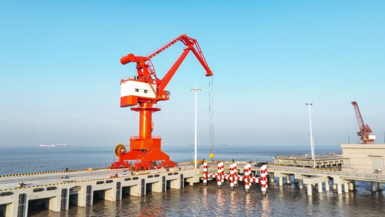
Official source gallery image associated with shipbuilding gantry-crane use in shipyard lifting and assembly work.
|

Official source gallery image associated with shipbuilding gantry-crane use in shipyard lifting and assembly work.
|

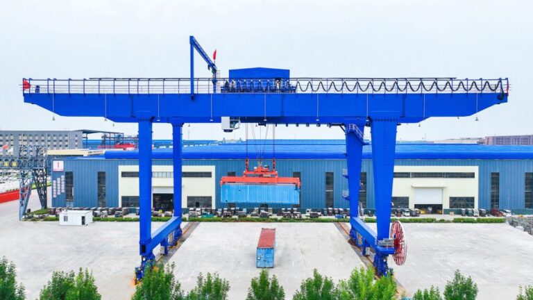
Official source gallery image associated with shipbuilding gantry-crane use in shipyard lifting and assembly work.
|

Official source gallery image associated with shipbuilding gantry-crane use in shipyard lifting and assembly work.
|
Main Crane Components
| Main Girder Structure |
Single- or double-main-girder portal structure selected around span, block weight, stiffness and shipyard layout. |
| Rigid Leg |
Provides one side of the portal support and transfers crane reactions to the rail / foundation. |
| Flexible Leg |
Works with the rigid leg on the opposite side according to the source-described gantry arrangement. |
| Hoisting / Trolley System |
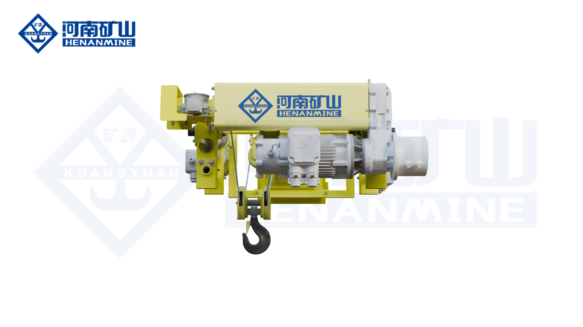
Configured around the ship-block lifting and turning process; exact trolley / hook arrangement is project-specific. |
| Gantry Travel System |
Moves the crane along dock or slipway rails. |
| PLC / Inverter Control |
Source-confirmed control architecture for crane motion. |
| Safety Monitoring System |
Source-confirmed data and video monitoring for complete-crane supervision. |
Technical Parameters
| Model |
MU |
| Product Type |
Shipbuilding Gantry Crane |
| Type-Test Product Name |
Shipbuilding Gantry Crane |
| Rated Capacity |
Project-specific |
| Span / Rail Gauge |
Project-specific |
| Lifting Height |
Project-specific |
| Runway Length |
Project-specific |
| Main Girder |
Single or double main girder |
| Leg Structure |
Rigid + flexible leg |
| Hoisting Speed |
Project-specific |
| Trolley Travel Speed |
Project-specific |
| Gantry Travel Speed |
Project-specific |
| Working Duty |
Project-specific |
| Block-Turning Arrangement |
Project-specific |
| Positioning / Synchronization |
Project-specific if required by the lifting method |
| Control Method |
PLC + inverter communication control; operator mode project-specific |
| Power Supply |
According to shipyard electrical conditions |
| Outdoor Wind / Corrosion |
According to actual coastal / shipyard environment |
Source-Confirmed Features & Buyer-Defined Options
Source-confirmed product facts:
- Model / type-test specification: MU.
- Type-test product name: Shipbuilding Gantry Crane.
- Installed on dock or slipway rails.
- Portal structure can use double main girders or a single main girder.
- Rigid and flexible legs are used in combination.
- Used for hull-section lifting, turning and assembly.
- Complete crane is equipped with a safety monitoring system.
- Complete crane uses PLC + inverter communication control.
- Main load-bearing members are designed with finite-element analysis.
- Safety monitoring includes data monitoring and video monitoring with transmission, acquisition, processing, storage and display functions.
- Buffer devices plus optimized hoisting and braking are used to reduce impact and vibration.
Buyer-defined items:
- Maximum hull-block weight including rigging / lifting frame
- Maximum hull-block length, width and height
- Center of gravity and lifting-lug coordinates
- Block turning / flipping method
- Single- or double-main-girder project layout
- Span / rail gauge, lifting height and runway length
- Required hook / lifting-point arrangement
- Positioning and synchronization requirements if applicable
- Shipyard operating cycle / working duty
- Wind, coastal corrosion and storm-protection conditions
- Control station / remote / cabin requirements
- Installation, testing and commissioning scope
Application Scenarios
| Hull Block Lifting |
Lift large prefabricated ship sections from fabrication / storage positions. |
| Ship Block Turning |
Support the defined turning or flipping process before final assembly. |
| Block Assembly / Erection |
Position ship sections for alignment and joining. |
| Dock / Slipway Handling |
Rail-mounted coverage over shipbuilding production areas. |
| Shipyard Heavy Lifting |
Project-specific handling of large shipbuilding structures and equipment. |
How to Select the Right MU Shipbuilding Gantry Crane
1. Start with the Heaviest Ship Block
Provide the maximum block weight plus all lifting frames, spreaders and rigging.
2. Provide the Largest Block Envelope
Length, width and height determine hook coverage, turning clearance and portal dimensions.
3. Provide Center of Gravity and Lifting Points
This data is critical when the block uses multiple lifting points or a turning process.
4. Define the Turning / Flipping Procedure
Show the starting orientation, final orientation, hook / attachment arrangement and the clearance required throughout the turn.
5. Define Span, Lift Height and Rail Layout
Provide dock / slipway drawings with rail gauge, rail elevation, travel length and assembly positions.
6. Define Production Duty
State blocks per shift, annual production plan, operating hours and typical load spectrum.
7. Define Positioning / Synchronization Acceptance
If the lifting arrangement requires multiple hooks or coordinated motion, state measurable allowable differences and acceptance tests.
8. Define Coastal / Outdoor Conditions
Provide design wind, operating wind, corrosion class or coating requirements and storm anchoring philosophy.
Ship Block Turning: What Buyers Must Define
| Block Weight |
Include the full suspended system, not only the steel block. |
| Block Dimensions |
Largest length, width and height across all block families. |
| Center of Gravity |
Required to calculate hook / lifting-point reactions. |
| Lifting-Point Coordinates |
Provide lug or spreader connection positions. |
| Turning Method |
Define the exact sequence and which lifting points change load during the turn. |
| Clearance Envelope |
Check block swing against ground, rails, legs, other blocks and shipyard equipment. |
| Allowable Tilt / Height Difference |
Project-specific if coordinated hooks or lifting points are used. |
| Acceptance Method |
Define how turning, alignment and synchronized motion will be tested. |
Single Girder or Double Girder?
| Source Position |
The official source states that the portal structure can use either a single main girder or double main girders. |
| Double-Girder Consideration |
May be selected when the project needs a structural / equipment arrangement that favors two main girders; final selection must come from engineering analysis. |
| Single-Girder Consideration |
May be selected when the project load, span, stiffness and equipment arrangement can be satisfied by a single-main-girder structure. |
| Buyer Decision |
Do not choose only by initial price. Compare block load, span, stiffness, trolley / hoist arrangement, access, erection and lifecycle maintenance. |
Safety Monitoring & Control
| PLC + Inverter Control |
Source-confirmed complete-crane communication control for smoother motion. |
| Safety Monitoring System |
Source-confirmed complete-crane system. |
| Data Monitoring |
Signal transmission, acquisition, processing, storage and display are source-listed. |
| Video Monitoring |
Source-confirmed as part of the safety monitoring system. |
| Finite-Element Design |
Main load-bearing components use FEA according to the source. |
| Impact / Vibration Reduction |
Buffers plus optimized hoisting and braking are source-listed. |
| Buyer-Specified Safety |
Overload, limits, emergency stop, anti-collision, wind / storm protection and any synchronization monitoring should be defined in the technical agreement where required. |
Installation & Maintenance
Before manufacture, confirm the dock or slipway rail gauge, rail elevation, runway length, foundation reactions, erection space, crane assembly method, electrical supply, block-handling zones and all shipyard obstacles. The largest block-turning envelope should be checked against the final gantry geometry before production.
Maintenance should follow the final supplied crane manual and the shipyard's lifting procedures. Routine attention should cover hoisting mechanisms, ropes, hooks / lifting frames, brakes, wheels, gantry travel, rails, structural connections, buffers, PLC/VFD equipment, safety-monitoring sensors and video-monitoring equipment.
What Information Do We Need for a Quote?
| 1 |
Maximum ship-block weight |
| 2 |
Largest ship-block length / width / height |
| 3 |
Center of gravity |
| 4 |
Lifting-lug / lifting-point coordinates |
| 5 |
Block turning / flipping procedure |
| 6 |
Required lifting frame / spreader / rigging data |
| 7 |
Span / rail gauge |
| 8 |
Lifting height |
| 9 |
Runway length |
| 10 |
Dock / slipway rail and foundation drawing |
| 11 |
Blocks per shift / operating hours / duty |
| 12 |
Required positioning / synchronization acceptance if applicable |
| 13 |
Control method |
| 14 |
Wind / corrosion / storm-protection requirements |
| 15 |
Power supply |
| 16 |
Shipyard layout |
| 17 |
Destination and erection / commissioning scope |
Frequently Asked Questions
What is the MU shipbuilding gantry crane used for?
The source identifies hull-section lifting, ship-block turning and assembly as the core applications.
Is the MU crane single girder or double girder?
The source states that the portal structure can use either double main girders or a single main girder. The final structure should be selected from the actual project.
Why are rigid and flexible legs used?
The source confirms a rigid-leg and flexible-leg combination as part of the shipbuilding gantry structure. Final structural behavior and rail reactions are determined by project engineering.
Does the source provide a standard capacity or span?
No. The source page does not publish one universal capacity or span, so these should be selected from ship-block and shipyard requirements.
What data is most important for block turning?
Block weight, dimensions, center of gravity, lifting points, turning sequence, required clearances and any coordinated-hook acceptance requirement.
What control functions are source-confirmed?
The source confirms PLC + inverter communication control, a complete-crane safety monitoring system, data monitoring and video monitoring.
What affects the quotation most?
Block weight and size, span, lifting height, runway length, turning / lifting arrangement, duty, wind / corrosion environment, control / monitoring scope and installation requirements.
Related Gantry Cranes
MG Double-Girder Hook Gantry Crane
ME New-Type Double-Trolley Gantry Crane
MGG Engineering Gantry Crane
Request A MU Shipbuilding Gantry Crane Quote
Send your ship-block weights and dimensions, lifting-point drawings, turning method, rail gauge, lifting height, runway length, dock / slipway layout, operating cycle and outdoor conditions. Henan Mine Crane engineers can then review the block-handling process and prepare a project-specific shipbuilding gantry crane configuration and quotation.
Request A Quote | View Gantry Cranes