Rubber-Tired Gantry Crane
Trackless, project-engineered lifting and transport for factories, precast yards, steel plants, wind-energy production, modular construction and other sites where heavy or oversized loads must move without a fixed rail runway.

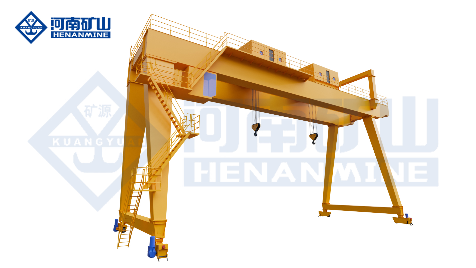
Rubber-tired gantry crane configured for flexible, rail-free movement in an industrial handling area.
Henan Mine Crane rubber-tired gantry cranes combine a load-bearing gantry, hoisting system and rubber-tired travel system in one mobile handling platform. Unlike a conventional rail-mounted gantry crane, the equipment can be engineered to move between work zones and serve changing production, storage and loading routes.
Capacity alone is not enough to select this equipment. The correct configuration depends on the complete suspended load, load dimensions, center of gravity, lifting points, required clear width, travel route, turning space, pavement capacity, operating frequency, power concept and environmental conditions. Parameters that have not been confirmed for a specific project are therefore identified as project-specific rather than assumed.
Quick Specifications
| Product Family |
Rubber-Tired Gantry Crane / Rubber-Tyred Gantry Crane / RTG |
| Travel Mode |
Rubber-tired, trackless mobile travel |
| Rated Capacity |
Configured from the maximum load plus spreader, lifting beam, slings and permanent attachments |
| Clear Width / Span |
Configured around the load envelope, travel aisle and pickup / placement geometry |
| Lifting Height / Under-Clearance |
Project-specific |
| Steering / Turning |
Selected from the actual route, aisle width and maneuvering zones |
| Travel Speed |
Project-specific for loaded and unloaded travel |
| Ground / Pavement Loading |
Project-specific; final tire and axle loads must be checked against the route |
| Working Duty |
Selected from load spectrum, moves per hour, travel distance and operating hours |
| Control Mode |
Project-specific according to visibility, route and automation requirements |
| Power / Drive |
Project-specific according to duty, travel range, site utilities and emissions requirements |
| Operating Environment |
Configured for actual indoor / outdoor temperature, wind, rain, dust, humidity and corrosion conditions |
Best For: Buyers who need one mobile lifting system to pick, transport and position heavy or oversized loads across multiple work zones without installing a permanent rail runway.
Request A Rubber-Tired Gantry Crane Quote
Product Overview
A rubber-tired gantry crane is both a lifting machine and a mobile transport system. Its gantry structure supports the suspended load, while the rubber-tired travel and steering systems allow the crane to move across prepared factory floors or outdoor yards without fixed rails. This makes it suitable for operations where loads must travel between production, inspection, storage and dispatch areas.
The equipment may be configured as an A-frame mobile gantry, double-beam rubber-tired gantry, industrial straddle carrier or a specialized handling platform. The most suitable form depends on whether the crane must travel over the load, lift from outside the load envelope, work under restricted headroom, pass through doors or turn inside narrow yards.
Before quotation, provide the maximum load drawing and a complete site route plan. Henan Mine Crane can then evaluate lifting capacity, structural clearance, steering geometry, ground loading, braking, duty and power requirements as one integrated system.
Why Choose a Rubber-Tired Gantry Crane?
Trackless Mobility
The crane is not limited to one fixed runway. A correctly engineered travel and steering system can serve multiple pickup, storage and loading points within the approved route.
Lower Rail-Infrastructure Dependency
Projects can avoid a continuous rail path, although the floor, pavement and ground structure must still be verified for loaded tire and axle reactions.
One Machine for Lifting and Transport
The same equipment can pick a load, move it through the approved route and position it at the destination, reducing intermediate transfers between separate lifting and transport machines.
Configured Around the Actual Load
Clear width, lifting height, spreader, lifting points and structural form can be engineered for long, wide, high or irregular loads that standard handling equipment cannot accommodate.
Flexible Production Layout
Rubber-tired travel is relevant where production routes, storage locations or project stages may change, provided every intended route is included in the engineering review.
Product Images

Building straddle carrier for lifting and transporting complete modular units through factory and loading routes.

Rubber-tired straddle carrier configured for lifting, yard transport and loading of precast concrete components.
Main Equipment Systems
| Gantry / Carrier Structure |
Engineered around capacity, load envelope, clear width, lifting height, travel stability and transport requirements. |
| Hoisting System |
Selected from the complete suspended load, number of lifting points, lift height, speed, synchronization and duty. |
| Spreader / Load Attachment |
Customized for the actual lifting points, center of gravity, load geometry and operating rules. |
| Rubber-Tired Travel System |
Configured for loaded and unloaded travel, route length, surface condition, gradients and required maneuverability. |
| Steering System |
Selected from aisle width, corner geometry, transfer route and alignment requirements. |
| Braking / Parking System |
Specified for maximum loaded mass, travel speed, route slope, stopping distance and safe parking conditions. |
| Power / Drive System |
Project-specific according to site utilities, travel distance, operating hours, energy targets and local environmental requirements. |
| Control / Operator System |
Configured according to operator visibility, positioning accuracy, travel route and required level of remote or automated control. |
| Safety / Monitoring System |
Defined through risk assessment and the final technical agreement, including lifting, travel, steering, braking and warning functions. |
Technical Parameters
| Product |
Rubber-Tired Gantry Crane |
| Alternative Search Names |
Rubber-Tyred Gantry Crane, RTG Crane, Tire-Mounted Gantry Crane, Industrial Straddle Carrier |
| Rated Capacity |
Project-specific |
| Clear Width / Span |
Project-specific |
| Lifting Height / Under-Clearance |
Project-specific |
| Overall Length / Width / Height |
Project-specific |
| Hoisting Speed |
Project-specific |
| Loaded / Unloaded Travel Speed |
Project-specific |
| Turning Radius / Steering Geometry |
Project-specific |
| Allowable Route Grade / Cross-Fall |
Project-specific |
| Tire / Axle Load |
Project-specific |
| Working Duty |
Project-specific |
| Lifting Attachment |
Project-specific for the actual load and lifting points |
| Control Mode |
Project-specific |
| Power / Drive |
Project-specific |
| Indoor / Outdoor Protection |
Project-specific |
Source-Confirmed Facts & Buyer-Defined Options
Source-confirmed product positioning:
- Product family: Rubber Tyred Gantry (RTG) / Tyre Gantry Crane.
- Core product direction: trackless mobility, heavy-load stability and intelligent energy-saving configuration.
- Target condition: heavy-duty handling where a fixed rail route is not preferred or available.
Buyer-defined items:
- Maximum load, load dimensions and center of gravity
- Lifting points and required attachment / spreader
- Clear width, lifting height and overall clearance limits
- Full loaded travel route, aisle widths and turning zones
- Floor, pavement or ground bearing information
- Moves per hour / shift and travel distance per cycle
- Steering, control, positioning and power requirements
- Indoor / outdoor wind, rain, dust, temperature and corrosion conditions
- Local design standard, power supply and acceptance requirements
- Delivery, commissioning, training and spare-parts scope
Application Scenarios
| Precast Concrete Yards |
Lift and transport beams, slabs, segments, culverts and other precast components between production, curing, storage and loading areas. |
| Modular Construction Plants |
Move complete room or building modules through constrained factory routes and position them for storage or vehicle loading. |
| Steel Mills / Fabrication Yards |
Handle long, heavy or oversized fabricated components where lifting points, load stability and yard conditions are defined. |
| Wind-Energy Manufacturing |
Transport large wind-turbine components between manufacturing, coating, inspection, storage and dispatch stations. |
| Shipyards / Heavy Manufacturing |
Move large structures, machinery, blocks or assemblies across multiple outdoor and indoor work zones. |
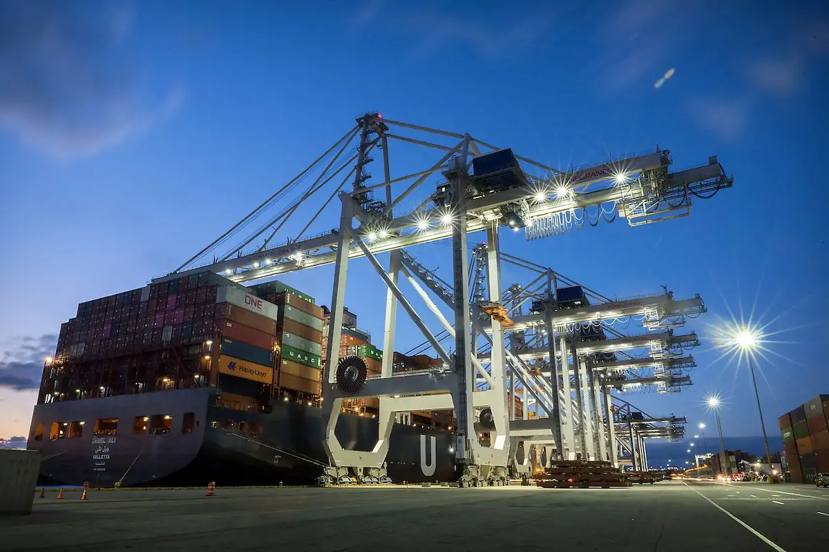
| Container / Logistics Yards |
Handle standardized containers when the crane, trolley, spreader, stacking layout, duty and control system are specifically engineered for container service. |
How to Select the Right Rubber-Tired Gantry Crane
1. Calculate the Complete Suspended Load
Include the heaviest load plus the spreader, lifting beam, slings, hooks and any permanent attachment. Do not select capacity from the cargo weight alone.
2. Provide the Load Envelope and Center of Gravity
Maximum length, width, height, center of gravity and lifting-point coordinates determine the gantry clearance, load attachment and stability review.
3. Map the Complete Travel Route
Show the narrowest aisle, door openings, corners, intersections, slopes, overhead obstructions, pickup points, placement points and parking area.
4. Verify Ground and Pavement Capacity
The complete loaded crane mass is transferred through a limited number of tires. Final tire and axle reactions must be checked against every section of the intended route.
5. Define Duty and Productivity
Provide moves per hour, hours per shift, shifts per day, loaded travel distance and load spectrum so the hoisting, drive, braking and maintenance strategy match real production.
6. Select the Operating Concept
Visibility, personnel access, route complexity and positioning accuracy determine the appropriate operator location, control functions and warning system.
7. Confirm Power and Environmental Requirements
Site utilities, travel range, emissions limits, operating time, outdoor exposure and local electrical conditions must be reviewed before the drive and power architecture is finalized.
Load & Route Data Buyers Must Provide
| Load Drawing |
Maximum L × W × H, weight, center of gravity and any protruding parts. |
| Lifting Points |
Coordinates, allowable reactions, lifting orientation and restrictions from the load designer. |
| Pickup / Placement Geometry |
Required hook or spreader position, support height, foundation, trailer or storage interface. |
| Route Layout |
Scaled plan showing all loaded travel paths, widths, corners, turning areas and operating zones. |
| Vertical Clearance |
Doors, roofs, pipes, cables, structures and any height restriction along the complete route. |
| Surface Information |
Slab or pavement capacity, surface type, joints, drains, rails, potholes, slopes and cross-fall. |
| Production Cycle |
Moves per hour / shift, loaded distance, unloaded return distance and expected operating hours. |
Configuration Options Buyers Should Compare
| Structural Form |
A-frame gantry, double-beam gantry, straddle carrier or another project-specific arrangement selected from load and route geometry. |
| Hoisting Arrangement |
Single-point, multiple-point or synchronized lifting selected according to load stiffness, lifting points and placement accuracy. |
| Attachment |
Hook, lifting beam, adjustable spreader, container spreader or a custom attachment verified for the load. |
| Steering / Maneuvering |
Selected from minimum aisle width, turning space, lateral alignment and route-change requirements. |
| Control Concept |
Operator and control arrangement selected from visibility, travel risk, positioning accuracy and site operating rules. |
| Energy / Drive Concept |
Compared by duty, route length, available utilities, charging / refueling strategy, emissions targets and lifecycle cost. |
Rubber-Tired Travel: What Buyers Should Confirm
| Minimum Route Width |
Measure the tightest gate, door, aisle, lane and crossing with the load in transport position. |
| Turning Space |
Show corners, intersections, reversing areas and the required approach direction at every workstation. |
| Slope / Cross-Fall |
Provide longitudinal grades and lateral slopes for all loaded travel and parking positions. |
| Surface Capacity |
Confirm slab, pavement or ground bearing capacity against the final tire and axle reactions. |
| Surface Condition |
Identify joints, potholes, loose material, rails, drains and transitions that can affect load stability or tire life. |
| Traffic Interface |
Define interaction with pedestrians, trucks, forklifts, production equipment and restricted zones. |
| Parking / Maintenance Area |
Provide a safe location for parking, isolation, inspection, tire work and access to service components. |
Safety & Control: What Buyers Should Confirm
• Rated-capacity and overload protection based on the complete suspended load
• Load stability during lifting, loaded travel, steering, braking and placement
• Hoisting limits, synchronization monitoring and emergency-stop functions where applicable
• Service braking, parking braking and safe holding on the approved route gradients
• Operator visibility, cameras, audible / visual warnings and restricted-zone management
• Tire condition, inflation / solid-tire requirements, wheel assemblies and axle-load verification
• Anti-collision, obstacle detection or positioning assistance where required by the risk assessment
• Outdoor wind monitoring, storm parking and weather protection where applicable
• Factory and site acceptance tests covering lifting, travel, turning, braking and safety functions
Installation, Commissioning & Maintenance
Before manufacture, freeze the load drawings, lifting points, route layout, minimum clearances, surface conditions, pickup / placement positions, operating cycle, applicable standard and site acceptance criteria. Because the equipment travels on tires, route readiness is part of installation planning even when no rail runway is required.
Commissioning should verify the crane on the approved route under the conditions defined in the technical agreement. Testing normally needs to cover lifting functions, loaded and unloaded travel, steering, alignment, stopping, parking, safety devices, warning systems and any required positioning or productivity targets.
Maintenance planning should include the hoisting system, ropes or chains where fitted, spreader, brakes, tires, wheel and axle assemblies, steering components, drive system, structural connections, controls and safety devices. Buyers should confirm service access, inspection intervals, recommended spare parts and local technical support before purchase.
What Information Do We Need for a Quote?
| 1 |
Maximum load weight, including all permanent lifting attachments |
| 2 |
Maximum load dimensions: length × width × height |
| 3 |
Center of gravity and lifting-point drawing |
| 4 |
Required spreader, lifting beam, sling or other attachment |
| 5 |
Required clear width and lifting height / under-clearance |
| 6 |
Full travel-route layout with minimum widths and turning areas |
| 7 |
Door openings, overhead restrictions and pickup / placement geometry |
| 8 |
Floor, pavement or ground bearing information |
| 9 |
Route slopes, cross-fall and surface-condition details |
| 10 |
Moves per hour / shift and loaded travel distance |
| 11 |
Control, operator and positioning requirements |
| 12 |
Available power supply and preferred drive concept, if specified |
| 13 |
Indoor / outdoor temperature, wind, rain, dust and corrosion conditions |
| 14 |
Destination country, local standard and power frequency |
| 15 |
Delivery, commissioning, testing, training and spare-parts scope |
Frequently Asked Questions
What is the difference between a rubber-tired gantry crane and a rail-mounted gantry crane?
A rubber-tired gantry crane travels on tires and is not limited to a continuous fixed rail route. A rail-mounted gantry crane follows installed rails and serves a defined runway. The better choice depends on layout flexibility, duty, positioning, infrastructure and lifecycle requirements.
Is every RTG crane designed for container handling?
No. RTG is also used for industrial rubber-tired gantries and straddle carriers handling precast components, steel structures, wind-energy parts, modular buildings and other oversized loads. Container service requires a container-specific spreader, stacking layout, duty and control system.
What determines the correct lifting capacity?
Use the maximum complete suspended load: cargo plus spreader, lifting beam, slings, hooks and any other attachment carried by the hoisting system.
Why is a route drawing required before quotation?
The crane must safely carry the load through the actual site. Aisle width, turning space, door openings, slopes, pavement and traffic interfaces can change the steering system, dimensions, tire loading, drive power and final price.
Can the crane be customized for irregular loads?
Yes, but the buyer must provide reliable load drawings, center-of-gravity data, lifting points and allowable reactions. The gantry clearance and lifting attachment are then engineered around those inputs.
What factors affect rubber-tired gantry crane price most?
Major cost drivers include lifting capacity, clear width, lifting height, structural form, steering requirements, tire and axle loading, spreader, duty, travel distance, control and power system, environmental protection and commissioning scope.
What should be included in the site acceptance test?
The technical agreement should define lifting, loaded travel, unloaded travel, steering, braking, parking, safety devices, warnings and any positioning or cycle-time requirements that are critical to the project.
Related Rubber-Tired Gantry Products
Wind Turbine Straddle Carrier
Steel Mill Straddle Carrier
Precast Concrete Straddle Carrier
Building Straddle Carrier
Straddle Carrier Crane
A-Frame Rubber-Tired Gantry Crane
Double Rubber-Tired Gantry Crane
Request A Rubber-Tired Gantry Crane Quote
Send the maximum load, complete load dimensions, center of gravity, lifting points, required clearances, full travel-route drawing, floor or pavement information and handling frequency. Henan Mine Crane can then review the lifting, structural, steering, ground-loading, drive and safety requirements together and prepare a project-specific technical proposal and quotation.
Request A Quote | View Gantry Cranes