Crane Span Explained: How to Measure It Without Costly Errors
Crane span is normally measured between the centerlines of the supporting runway rails or tracks—not between building walls, column faces or rail edges. Confirm the reference for the selected crane type, survey the runway at multiple locations and obtain manufacturer approval before manufacturing begins.
The Direct Answer: Measure Centerline to Centerline
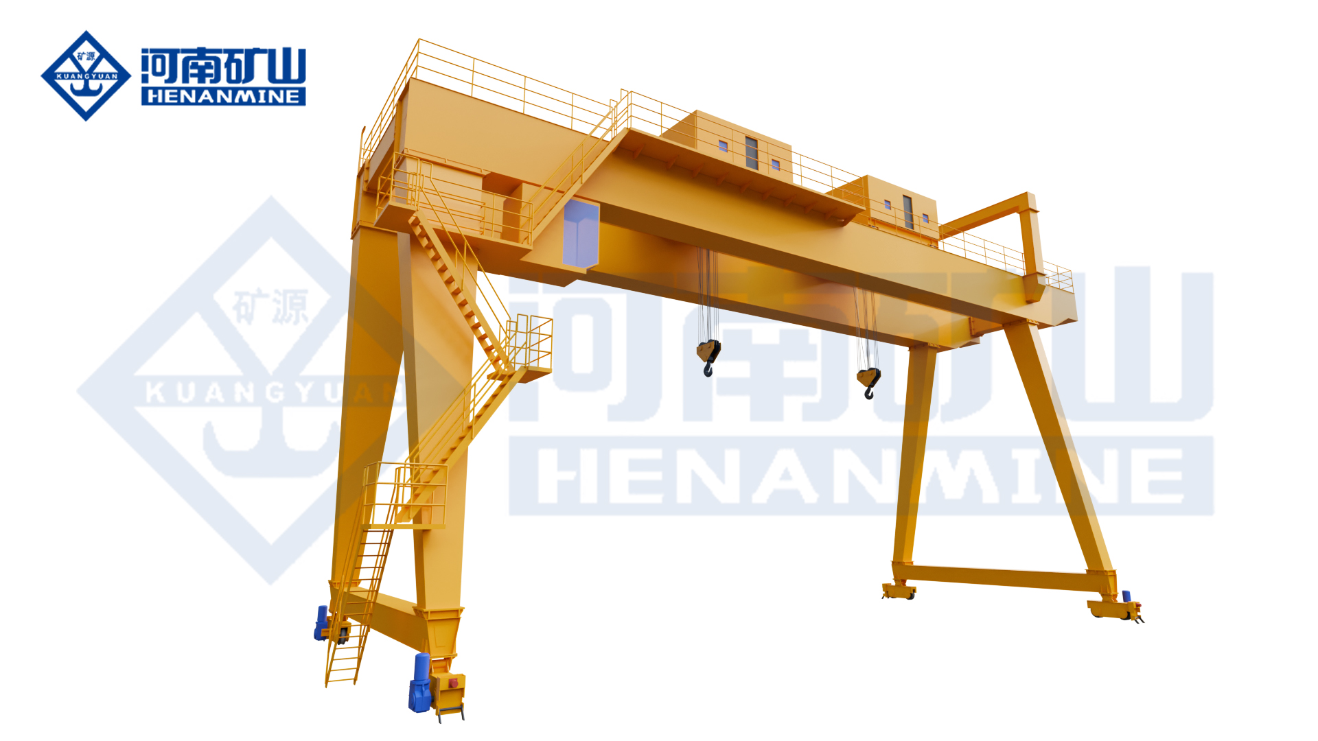
For a typical top-running overhead crane, span is the horizontal distance between the centerline of one runway rail and the centerline of the opposite runway rail. For an underhung crane, span is normally measured between the centerlines of the suspended runway tracks. For a rail-mounted full gantry crane, span is normally measured between the travel-rail centerlines. The project drawing and manufacturer must confirm the exact reference.
Do not use clear building width, column spacing, inside rail-edge distance, outside rail-edge distance, bridge overall length or hook coverage as a substitute for crane span. These are separate dimensions. An incorrect span can change girder length, end-truck geometry, wheel alignment, clearances, runway reactions, transport planning and installation cost.
Correct Span Information
- Identify the crane type and running arrangement.
- Show both rail or track centerlines on the drawing.
- Measure at multiple stations along the runway.
- Record rail/track elevation and condition with span.
- State whether dimensions are surveyed, nominal or provisional.
Dimensions That Are Not Crane Span
- Clear width between walls or columns.
- Building grid or runway-beam spacing.
- Inside-to-inside or outside-to-outside rail edges.
- Crane bridge overall length or end-truck wheelbase.
- Usable hook coverage or side approach.


1. Use the Correct Span Definition for Each Crane Layout
| Crane Layout | Normal Span Reference | Additional Dimensions Required | Common Error |
|---|---|---|---|
| Top-running overhead crane | Centerline of one runway rail to centerline of the opposite rail. | Rail section, elevation, runway-beam width, wall/column clearance and roof envelope. | Using building clear width or rail inside edges. |
| Underhung overhead crane | Centerline of one suspended runway track to centerline of the opposite track. | Track section, flange geometry, lower-flange elevation, support/hanger positions and roof services. | Measuring between inner flange edges or support-beam faces. |
| Rail-mounted full gantry crane | Centerline of one travel rail to centerline of the opposite travel rail. | Clear leg opening, cantilevers, wheel arrangement, foundation, vehicle/load envelope and rail elevation. | Using clear space between legs or crane overall width. |
| Semi-gantry crane | Centerline of the elevated runway rail to centerline of the ground travel rail. | Vertical elevation difference, building interface, ground foundation and relative settlement. | Ignoring the mixed support elevations or measuring to a wall face. |
| Rubber-tired gantry / straddle carrier | Project-specific wheel-path or structural reference confirmed by the supplier. | Clear width, overall width, tire/axle geometry, turning envelope and load overhang. | Assuming rail-mounted span terminology applies unchanged. |
Span Is Not Hook Coverage
Hook coverage is reduced by trolley side approach, bridge end approach, end stops, buffers and equipment geometry. A 20 m crane span does not provide 20 m of transverse hook travel or a hook centerline directly against the wall. Define pickup and placement coordinates separately.
Span Is Not Overall Crane Length
The bridge extends beyond runway centerlines to connect with end trucks, wheels, buffers, drives, platforms and clearances. Overall crane length is an engineering output from the selected end-truck arrangement; it is not the span supplied by the buyer.
Use the top-running vs underhung crane guide and the full-gantry vs semi-gantry guide to confirm the support arrangement before finalizing the span reference.
2. How to Measure Span on an Existing Runway
An existing runway should be surveyed as a coordinate system, not checked with one tape measurement. Use a qualified survey method and instruments suitable for the height, length and access conditions. Work under the owner’s isolation, access and fall-protection procedures.
1Establish Datums and Survey Stations
Choose a building gridline or longitudinal datum, a finished-floor or benchmark elevation and a runway origin. Identify stations near both ends and at enough intermediate column/support lines to show how gauge, alignment and elevation change along the runway.
2Locate the Actual Rail or Track Centerline
Identify rail/track section, head or flange width, wear and mounting. Do not aim at an inside edge on one side and an outside edge on the other. If edge measurements are unavoidable, record the exact reference and measured section so centerlines can be calculated correctly.
3Measure Gauge at Multiple Stations
Record each centerline-to-centerline reading individually. Do not average the readings and discard the range. Variation may indicate nonparallel rails, local movement, installation error, wear or building settlement. The manufacturer and runway engineer need the minimum, maximum and station-by-station data.
4Survey Elevation and Alignment at the Same Stations
Span alone does not confirm runway condition. Record rail/track elevation, longitudinal alignment, joint condition, steps, visible wear, fasteners and support condition. Relative elevation and alignment affect wheel loading, skewing, drive behavior and installation.
5Document Confidence and Measurement Conditions
State the instrument/method, units, survey date, accessible and inaccessible areas, assumed points and whether the runway carried load during measurement. For sensitive long-span or high-temperature projects, record any survey conditions requested by the responsible engineer.
3. How to Define Crane Span for a New Building or Yard
For a new project, span is coordinated between the material-handling process, building grid, runway structure and crane design. Begin with the required hook service area and load route; then allow for trolley approaches, bridge clearances, columns, walls, platforms, utilities and maintenance access. The final rail centerlines should be frozen on an approved interface drawing.
Start With Process Coordinates
- Load pickup and placement centerlines.
- Machine, rack, truck and storage interfaces.
- Required side/end hook approaches.
- Load and rigging envelope.
- Future equipment or expansion allowance.
Coordinate the Structural Interface
- Building column and runway-beam locations.
- Rail section, support width and centerlines.
- Crane and runway design reactions.
- Roof, wall, bracing and utility clearances.
- Installation and future removal route.
Do Not Freeze the Building Before Reviewing the Crane Envelope
A wider span can increase girder depth, crane weight, wheel reactions, wind area, transport segmentation and erection complexity. A narrower span can reduce hook coverage or force expensive process changes. Review preliminary crane drawings while building and equipment layouts can still be adjusted.
Survey the Completed Runway Before Final Acceptance
Design drawings define intended rail centerlines; they do not prove the installed runway matches them. Survey the completed rails/tracks and resolve deviations before crane installation or final commissioning.
For a complete site-measurement package, use the internal crane span, runway length, lifting height and clearance guide.
4. Span Measurement Errors That Increase Project Cost
| Error | What Can Happen | Corrective Action |
|---|---|---|
| Using clear building width as span | Bridge length and end trucks are based on the wrong reference; crane may not fit the rails. | Show rail/track centerlines and survey their actual coordinates. |
| Measuring one runway station | Nonparallel rails or local deviations remain hidden, leading to skewing, flange wear or installation conflict. | Survey multiple stations and report the complete range. |
| Mixing rail-edge references | The result includes or excludes one or two rail widths unpredictably. | Use centerlines or record exact edge references and rail dimensions. |
| Copying an old crane drawing | The runway may have moved, been repaired or never matched the original drawing. | Use legacy drawings as reference and verify the installed condition. |
| Sending only an average span | Supplier cannot judge runway variation or determine whether correction is needed. | Send every station reading, minimum, maximum and nominal design value. |
| Ignoring hook approaches | Crane fits the runway but cannot reach machines, trucks, molds or storage locations. | Specify required hook coordinates separately from span. |
| Approving manufacture before interface review | Late changes affect steelwork, runway, shipping, erection and schedule. | Approve the final general arrangement and interface schedule first. |
5. Convert Survey Data Into an Approved Crane Span
The survey provides actual runway coordinates; it does not automatically define the manufacturing dimension. Henan Mine Crane reviews the nominal span, survey range, rail/track section, runway condition, selected end trucks, wheels, clearances and applicable tolerances before issuing the crane general arrangement.

| Approval Item | What Must Be Confirmed | Responsible Interface |
|---|---|---|
| Nominal crane span | Manufacturing reference between approved runway centerlines. | Crane manufacturer with buyer/runway confirmation. |
| Runway gauge and alignment | Installed range, parallelism, elevation, rail section, joints and condition. | Qualified survey and runway/structural parties. |
| Clearances | Bridge/end-truck envelope, roof, walls, columns, utilities and maintenance access. | Crane, building and installation teams. |
| Hook coverage | Side/end approaches and pickup/placement coordinates. | Buyer process team and crane manufacturer. |
| Tolerances | Applicable manufacturing, runway and installation tolerances stated separately. | Project engineering team under the selected standards. |
| Final drawings | Span, overall dimensions, wheel arrangement, reactions, power interface and installation points. | Manufacturer approval workflow with buyer sign-off. |
Do Not Use a Universal Span Tolerance
Allowable deviation depends on the crane type, span, wheel arrangement, rail/track system, applicable standard and project specification. Manufacturing tolerance for the crane and installation tolerance for the runway are not the same. Require both to be stated in the technical agreement.
Approve One Controlled General Arrangement
The final general arrangement should show rail/track centerlines, crane span, overall bridge/end-truck dimensions, hook approaches, clearances, rail elevation, wheel reactions and reference datums. This drawing should align the crane supplier, building engineer, runway contractor and installation team.
6. Crane Span Measurement Worksheet
Record enough detail for a manufacturer to understand the measurement—not only the final number.
| Station / Gridline | Rail/Track Center Distance | Left Elevation | Right Elevation | Rail / Support Notes |
|---|---|---|---|---|
| Runway start | Surveyed value | Surveyed value | Surveyed value | End stop, joint, wear, fasteners, access. |
| Column/support station | Surveyed value | Surveyed value | Surveyed value | Rail section, beam/bracket condition, obstruction. |
| Intermediate station | Surveyed value | Surveyed value | Surveyed value | Alignment, joint, damage or measurement restriction. |
| Runway end | Surveyed value | Surveyed value | Surveyed value | End stop, buffer, wall and installation clearance. |
7. How Span Changes Crane Configuration and Cost
Girder Depth and Weight
Increasing span usually increases structural demand and can change girder depth, bridge weight, wheel loads, deflection, fatigue design and transport segmentation.
Single vs Double Girder
Span influences girder selection but does not decide it alone. Capacity, lifting height, duty, hook approach, trolley arrangement, maintenance and runway capacity must be evaluated together.
Headroom and Lift Height
A deeper bridge or different trolley arrangement can affect crane height and highest hook position. Coordinate span with rail elevation, roof clearance and required lifting height.
Runway and Foundations
Span changes bridge weight and wheel reactions. Building columns, runway beams, brackets, foundations or gantry rails must be checked using project-specific manufacturer reactions.
Use the single-girder vs double-girder overhead crane guide, the overhead crane selection guide and the gantry crane selection guide to evaluate span together with capacity, lift, duty and site interfaces.
8. Span and Runway Information to Include in the RFQ
Provide the span package with the other data listed in what a crane manufacturer needs before quoting and the overhead crane RFQ checklist.
Coordinate survey access, runway correction, installation route, power and safe erection using the crane installation planning checklist.
9. Frequently Asked Questions
Is crane span the same as building width?
No. Crane span normally follows runway rail or track centerlines. Building clear width, column spacing and overall bay width are separate dimensions.
Can span be measured between the inner rail edges?
Direct centerline surveying is preferred. An edge measurement is only useful if the exact edges and rail/track widths are recorded and the center-to-center value is calculated correctly.
Is one span measurement enough?
No. Measure at multiple stations because rails/tracks may not be parallel and the gauge may vary along the runway. Record every reading rather than only an average.
Can the new crane use the span from the old crane drawing?
Use it as reference, but survey the actual runway. The installed rails may differ from the old drawing or may have changed through repairs, wear, settlement or previous modification.
What if runway gauge changes along its length?
Send all measurements to the crane manufacturer and runway engineer. They must determine whether the runway needs correction and which nominal crane span and tolerances are acceptable. Do not simply manufacture to the average.
What is the allowable crane span tolerance?
It is project-specific and depends on crane type, span, wheel arrangement, runway system and governing requirements. Ask the supplier to state crane manufacturing and runway installation tolerances separately.
Does a 20 m span provide 20 m of hook travel?
No. Hook travel is reduced by trolley side approaches and other crane geometry. Specify required hook coordinates independently from span.
How should span be defined before new rails are installed?
Use the coordinated design rail centerlines as a provisional span, obtain manufacturer review and survey the completed runway before installation and final acceptance.
Final Recommendation
Confirm the Correct Centerline Reference
Identify top-running, underhung, gantry or semi-gantry support architecture before any span number is issued.
Survey the Complete Runway
Measure center distance, alignment and elevation at multiple stations and record the full range.
Keep Span and Hook Coverage Separate
Specify process pickup and placement coordinates so the selected crane can reach the required work area.
Approve the General Arrangement Before Manufacturing
Confirm span, end-truck envelope, hook approaches, clearances, reactions, runway data and tolerances on one controlled drawing.
Send Your Span Survey for a Crane Layout Review
Send Henan Mine Crane your runway centerline survey, rail/track section, elevations, building plan and cross-section, required hook coordinates, capacity, lifting height, duty, clearances and installation access. Our technical sales and engineering teams can identify missing measurements and prepare a project-specific crane layout and quotation.
Request a Crane Layout and Quotation
Review Crane Lifecycle Services