QP Grab & Electromagnetic Dual-Purpose Overhead Crane
For mixed-material facilities that need one double-girder crane to handle bulk material by grab and magnetic steel with an auxiliary hook-mounted electromagnet.

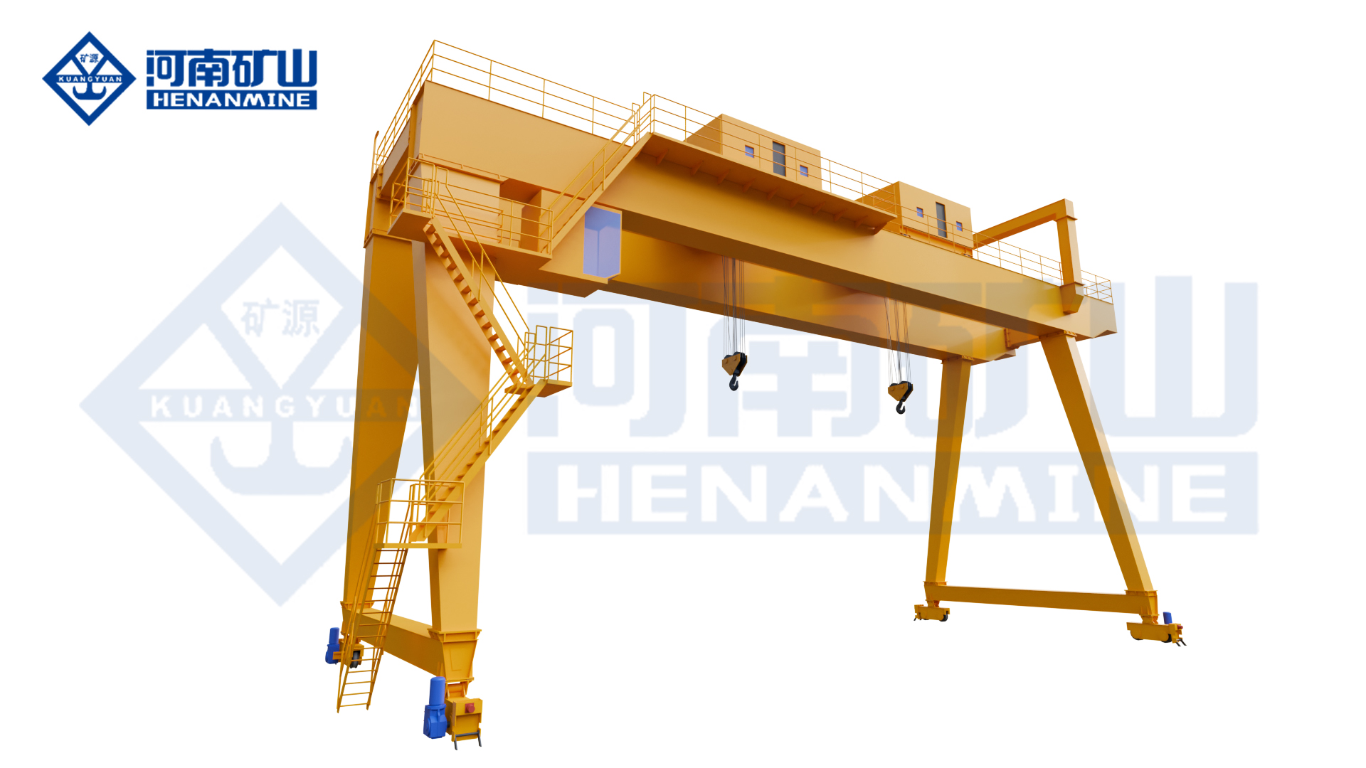
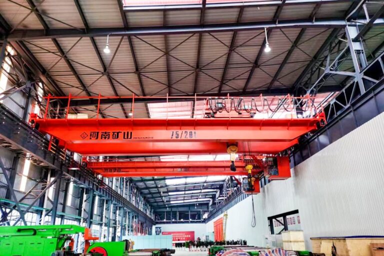
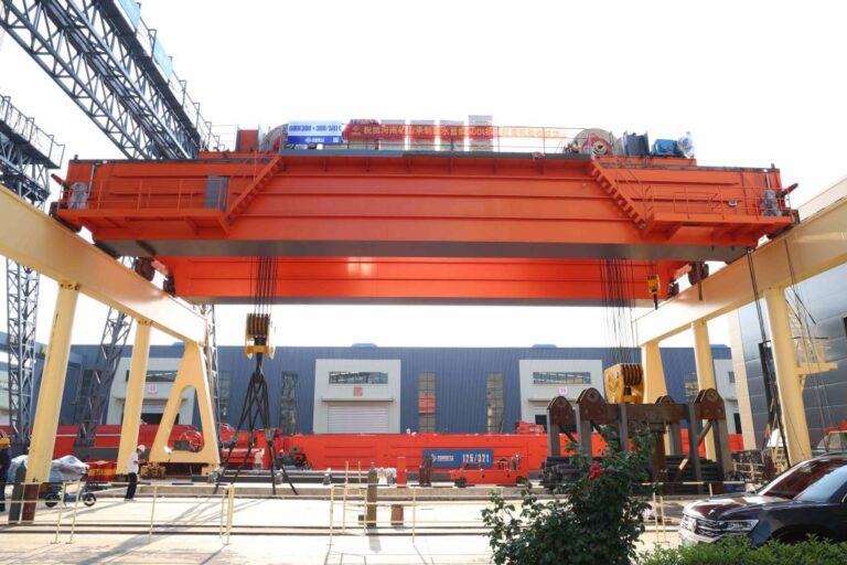
Henan Mine Crane qp grab & electromagnetic crane showing the primary crane structure and lifting arrangement.
The QP dual-purpose crane is a double-main-girder, single-trolley bridge crane with main and auxiliary hoisting. The main hoist uses two winch mechanisms to control the grab support and closing ropes. The auxiliary hoist uses a hook carrying an electromagnetic lifter.
Buyers should separate the two load cases in the RFQ: bulk-material grab duty and electromagnetic steel duty have different throughput, load and attachment requirements. The crane should be sized for the governing load and duty while maintaining safe mode changeover.
Quick Specifications
| Product Model |
QP |
| Type-Test Product Name |
General Overhead Crane |
| Lifting Capacity |
Configured according to project requirements |
| Span |
Configured according to runway center distance |
| Lifting Height |
Configured according to workshop / process requirements |
| Working Duty |
Configured from source data and actual load spectrum |
| Lifting Attachment |
Configured according to the product and load |
| Control Method |
Configured according to project requirements |
| Source-Stated Connector Protection |
IP55 |
| Source-Stated Wheel-Life Improvement |
About 20% vs traditional forged-wheel process (source claim) |
Best For: For mixed-material facilities that need one double-girder crane to handle bulk material by grab and magnetic steel with an auxiliary hook-mounted electromagnet.
Request A QP Grab & Electromagnetic Crane Quote
Product Overview
Double main girder, single trolley, main and auxiliary hoisting.
Main hoist uses two identical winch mechanisms for grab support and closing ropes.
Auxiliary hoist uses one motor, reducer and double brakes; hook carries electromagnetic lifter.
Where the source page does not publish a numerical capacity, span, speed, duty, positioning accuracy or other guaranteed performance value, the final value should be selected and agreed from the actual project rather than copied from a similar crane.
Why Choose QP Grab & Electromagnetic Crane?
Bulk + Magnetic Steel Handling
One crane serves two very different material streams.
Dedicated Grab Winches
Support and closing ropes are separately controlled by dual winch mechanisms.
Auxiliary Magnet Hoist
Magnetic lifting remains available without replacing the main grab system.
Quick Electrical Conversion
IP55 aviation-plug connection supports reliable attachment electrical changes.
Cab + Remote Control
Source allows both operator arrangements.
Product Images

Source image associated with the QP Grab & Electromagnetic Crane, showing the crane, magnetic attachment or steel-handling application.
|

Source image associated with the QP Grab & Electromagnetic Crane, showing the crane, magnetic attachment or steel-handling application.
|

Source image associated with the QP Grab & Electromagnetic Crane, showing the crane, magnetic attachment or steel-handling application.
|

Source image associated with the QP Grab & Electromagnetic Crane, showing the crane, magnetic attachment or steel-handling application.
|

Source image associated with the QP Grab & Electromagnetic Crane, showing the crane, magnetic attachment or steel-handling application.
|

Source image associated with the QP Grab & Electromagnetic Crane, showing the crane, magnetic attachment or steel-handling application.
|
Main Crane Components
| Bridge Structure |
Engineered from capacity, span, duty, runway and product-specific process loads. |
| Hoisting / Trolley System |
Configured for the product's lifting mechanism and operating cycle. |
| Lifting Attachment |
Selected from the actual load geometry, material and process. |
| Travel System |
Bridge and trolley travel selected for required speed, duty and positioning. |
| Electrical & Control System |
Configured for operator control, safety functions and any source-supported automation / monitoring. |
Technical Parameters
| Model |
QP |
| Product Type |
QP Grab & Electromagnetic Dual-Purpose Overhead Crane |
| Type-Test Product Name |
General Overhead Crane |
| Capacity |
Project-specific unless source-stated above |
| Span |
Project-specific unless source-stated above |
| Lifting Height |
Project-specific |
| Hoisting Speed |
Project-specific |
| Trolley / Crane Travel Speed |
Project-specific |
| Working Duty |
Project-specific unless source-stated above |
| Control Method |
Project-specific |
| Power Supply |
According to site electrical conditions |
| Operating Environment |
According to actual process conditions |
Source-Confirmed Features & Buyer-Defined Options
Source-confirmed product facts:
- Double main girder, single trolley, main and auxiliary hoisting.
- Main hoist uses two identical winch mechanisms for grab support and closing ropes.
- Auxiliary hoist uses one motor, reducer and double brakes; hook carries electromagnetic lifter.
- Cab and remote control are source-listed.
- PLC module, HMI touch screen and WLK master controller are source-listed.
- Heavy-duty aviation-plug electrical connection is source-listed with IP55 protection for quick grab/electromagnet conversion.
- Source reports forged/rolled wheel process with about 20% longer life than traditional forged-wheel process.
Buyer-defined items:
- Capacity and total suspended load
- Span / lifting height / runway length
- Load geometry and lifting attachment
- Operating frequency and working duty
- Control and safety functions
- Positioning / synchronization / automation where applicable
- Installation, testing and commissioning scope
Application Scenarios
| Bulk Raw Materials |
Grab handling of loose material. |
| Steel Scrap / Magnetic Material |
Electromagnetic auxiliary handling. |
| Mixed-Material Plants |
One crane serving bulk and steel tasks. |
| Warehouses / Process Yards |
Flexible mode selection. |
How to Select the Right QP Grab & Electromagnetic Crane
1. Define Grab Material / Throughput
Bulk density and cycles determine grab duty.
2. Define Electromagnetic Load
Material type and magnet arrangement determine auxiliary load.
3. Define Simultaneous / Sequential Use
Clarify whether main and auxiliary systems ever operate together.
4. Define Attachment Connections
Confirm power and quick-connect requirements.
5. Define Control Modes
Specify cab, remote and safe mode-selection logic.
Two Load Cases, One Crane
| Grab Duty |
Define bulk material, throughput and grab load. |
| Electromagnetic Duty |
Define magnetic material, magnet arrangement and backup-power needs if required. |
| Main / Auxiliary Hoists |
State whether simultaneous use is permitted or required. |
| Mode Changeover |
Define electrical / procedural interlocks during attachment changes. |
Safety & Control: What Buyers Should Confirm
• Rated capacity, overload protection and load-indication requirements
• Hoisting / travel limits, braking and emergency-stop requirements
• Attachment-specific safety such as magnet backup, grab interlocks, clamps or tandem synchronization where applicable
• Operator control method, visibility and safe access
• Anti-collision, anti-sway, positioning or automation requirements where required by the process
• Factory / site acceptance, load tests and project-specific functional tests
Installation & Maintenance
Before manufacture and installation, confirm runway span, rail / runway-beam condition, elevation, straightness, available headroom, power supply and erection access. Special attachments, multi-trolley systems, cantilevers, suspended runways and automated layouts should be coordinated with the workshop or yard drawing before production.
Maintenance should follow the supplied crane manual and actual duty. Inspection normally covers the hoisting mechanism, brakes, ropes, hooks / attachments, wheels, drives, fasteners, limits and electrical systems, with additional checks for magnets, grabs, clamps, sensors, encoders or automation hardware where fitted.
What Information Do We Need for a Quote?
| 1 |
Bulk material / density |
| 2 |
Grab self-weight / volume |
| 3 |
Magnetic material / maximum load |
| 4 |
Magnet self-weight |
| 5 |
Main / auxiliary load requirements |
| 6 |
Span / lift / runway length |
| 7 |
Duty for each mode |
| 8 |
Cab / remote requirement |
| 9 |
Attachment electrical interface |
| 10 |
Power supply |
| 11 |
Workshop layout |
| 12 |
Destination |
Frequently Asked Questions
How is the final crane capacity selected?
Use the total suspended load, including the load itself plus any beam, grab, magnet, clamp, spreader or rigging that remains below the hook.
Can the capacity, span and lifting height be customized?
Yes, these values are project-specific unless a source range is explicitly listed on this page. Provide the workshop / yard data for engineering selection.
What should I provide for a faster quotation?
Provide load drawings or dimensions, maximum suspended load, span, lifting height, runway length, operating cycle, environment and the specific process function that makes this product necessary.
Can control and automation be customized?
Where the source supports PLC, VFD, positioning, WMS/MES/DCS or remote functions, the final scope should be defined from the buyer's interface and acceptance requirements.
How should source-reported performance numbers be treated?
They describe the source product configuration. Any value that matters contractually for a new project should be written into the technical agreement and acceptance plan.
Related General Overhead Cranes
QLC Lower-Rotating Electromagnetic Beam Overhead Crane
QJ Lower-Rotating Beam Overhead Crane
QZ Intelligent Grab Bucket Double-Girder Overhead Crane
QEN Grab & Hook Dual-Purpose Overhead Crane
QDXG Zinc Pot Maintenance Overhead Crane
Request A QP Grab & Electromagnetic Crane Quote
Send your lifting load, span, lifting height, runway length, workshop or yard drawing, operating cycle, load geometry and special attachment / control requirements. Henan Mine Crane engineers will review the process and prepare a project-specific crane configuration and quotation.
Request A Quote | View Overhead Cranes