Lifting Height vs Headroom vs Hook Approach: What Buyers Need to Specify
Lifting height is the hook's required vertical travel. Headroom is the vertical space needed between the highest hook position and an agreed crane, beam, rail or building reference. Hook approach normally describes the horizontal distance from the hook centerline at its travel limit to a wall, runway, crane end or other defined boundary. Buyers must state all three with exact datums and hook coordinates.
The Direct Answer: These Three Dimensions Are Not Interchangeable
A crane can have sufficient lifting height but inadequate headroom. It can also achieve the required highest hook position while failing to reach a machine near the wall because its hook approach is too large. Capacity, span and building height do not prove that the crane can complete the handling process.
The most reliable purchase specification uses a single coordinate system. Establish a finished-floor or surveyed elevation datum, identify the runway rail or support-beam reference, and mark every required hook-center position on a plan and cross-section. Then ask each manufacturer to show the upper and lower hook limits, moving equipment envelope and horizontal hook limits on the project-specific general arrangement.
| Term | Buyer Definition | Required Reference | What It Proves |
|---|---|---|---|
| Lifting height | Required vertical travel between the lowest and highest hook-center positions. | Both hook elevations measured from the same project datum. | Whether the hook can travel between the lowest pickup and highest placement positions. |
| Headroom | Vertical space consumed above the highest hook position or required around the crane, using a stated equipment/support datum. | Rail top, beam top, underside of beam, or another clearly drawn reference. | Whether the selected crane and hoist fit below the roof and overhead services while achieving the required upper hook position. |
| Hook approach | Horizontal distance from the hook centerline at its travel limit to an agreed side or end reference. | Wall, column/gridline, runway rail centerline, crane end, end stop, gantry leg or process centerline. | Whether the hook can reach every pickup and placement coordinate near the sides and ends of the operating area. |

1. Lifting Height: Specify Hook Travel, Not Building Height
Lifting height is normally the vertical distance between the lowest operating hook-center position and the highest operating hook-center position. If elevations increase upward and both positions use the same datum, the required lifting height is:
Use project coordinates and confirm how upper and lower limit-switch stopping positions affect the usable travel.
Define the Highest Hook Position from the Process
Start at the highest receiving or installation point. Add the load height, lifting-point location, sling or below-the-hook device geometry and the handling allowance needed to clear surrounding equipment. The required hook elevation is determined by the suspended load system—not by the empty hook alone.
Define the Lowest Hook Position Independently
Check floor pickups, truck beds, pits, maintenance openings and any future lower level. A crane can provide an excellent upper hook position but still lack enough rope travel to reach a pit. The hoist drum, reeving and rope length must be selected from the complete vertical travel.
Include the Below-the-Hook Equipment
Permanent grabs, magnets, spreader beams, clamps, lifting beams and rotating devices consume vertical space and may be included in or separate from the rated load depending on the technical agreement. State their height, mass, lifting points and storage position. For multiple attachments, identify which configuration governs lifting height and which governs capacity.
| Buyer Input | Information Required | If Missing |
|---|---|---|
| Highest pickup or placement | Surface elevation, load height, lifting-lug position and rigging height. | The hook may reach the quoted height while the load cannot clear or land. |
| Lowest pickup | Floor, pit or vehicle elevation plus the required hook connection position. | Drum and rope travel may be insufficient. |
| Limit positions | Usable operating limits and any final protective limits shown separately. | Catalog travel may be mistaken for usable production travel. |
| Future operating level | Planned platforms, pits, machines or loading elevations. | Later process changes may require costly rope, drum or crane modification. |
Use the crane span, runway length, lifting height and clearance measurement guide to prepare the complete building dimension package.
2. Headroom: State the Vertical Datum and the Complete Moving Envelope
“Headroom” is frequently used with different reference points. For an electric hoist on a monorail, it may describe the distance from the underside of the beam or trolley running surface to the highest hook center. For an overhead crane, a buyer may use it for the distance from rail top to the highest hook center, or for the clearance from crane top to the lowest roof obstruction. These are different dimensions.
The solution is not to debate terminology. Require the supplier to identify every datum on the drawing and provide the actual coordinates of the highest hook center and highest moving equipment point.
Vertical Data the Manufacturer Needs

Do Not Use a General Headroom Reduction Percentage
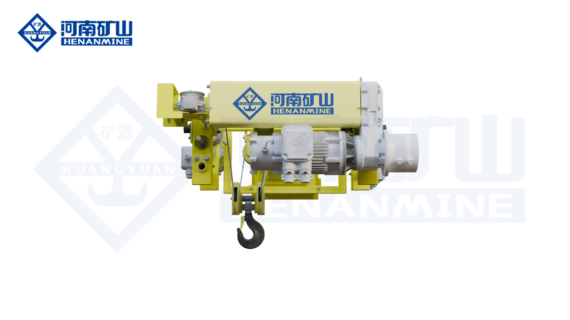
Any claimed improvement must use the same capacity, lifting height, duty, beam or rail interface, hook block and datum. A compact hoist may improve the upper hook position, but the final crane bridge, trolley, power feed and maintenance arrangement determine whether the building fit is acceptable. Compare dimensioned layouts rather than marketing labels.
For restricted buildings, review the KS1 low-headroom wire rope electric hoist and the low-headroom electric single-girder crane as project-specific alternatives to a standard arrangement.
3. Hook Approach: Define Left, Right and Both Runway Ends
Hook approach determines the unreachable area near the boundaries of the crane's travel. It is not the same as span, runway length or building bay width. A supplier cannot confirm hook approach from capacity alone because the value depends on trolley geometry, end-carriage dimensions, buffers, end stops, drives, platforms, conductors, gantry legs and surrounding structures.
| Approach Dimension | Normal Meaning | Reference to State | Buyer Use |
|---|---|---|---|
| Left trolley side approach | Hook center at the left trolley limit to the agreed left boundary. | Left runway rail centerline, wall/gridline or process centerline. | Confirms access to machines, racks or transfer points near the left side. |
| Right trolley side approach | Hook center at the right trolley limit to the agreed right boundary. | Right runway rail centerline, wall/gridline or process centerline. | Identifies asymmetry caused by motor, drum, cab, platform or trolley arrangement. |
| End approach A | Hook center at the bridge travel limit near runway end A. | End wall/gridline, rail end, end stop or process transfer line. | Confirms access to loading points, doors and equipment at the first runway end. |
| End approach B | Hook center at the bridge travel limit near runway end B. | End wall/gridline, rail end, end stop or process transfer line. | Confirms the opposite end even when end-stop or building geometry differs. |
| Vertical / upper hook approach | Sometimes used to describe headroom or the highest hook relationship. | Must be drawn from a named beam or rail reference to the hook center. | Prevents the word “approach” from being confused with horizontal coverage. |
Hook Coverage Must Be Shown as Coordinates
Mark each required pickup and placement centerline on the building plan. Show the hook's maximum transverse and longitudinal coordinate limits on the same drawing. This is more reliable than stating “minimum side approach” because the left and right values may differ and because the nearest wall may not be the correct process reference.
Allow for the Load and Rigging Envelope
The hook center may reach a coordinate while the load collides with a column, wall, machine or gantry leg. Add load width, sling angle, load rotation, center-of-gravity offset and operating allowance. For long loads, confirm the entire swept envelope rather than only the hook path.
4. How Crane Layout Changes All Three Dimensions
There is no universal layout that provides the best lifting height, headroom and hook approach at the lowest cost. Crane type, girder arrangement, trolley design and runway elevation must be compared against the building and handling process.
| Crane Layout | Vertical Consideration | Hook Approach Consideration | Buyer Decision |
|---|---|---|---|
| Top-running single-girder crane | Bridge and hoist arrangement determine highest hook position below or relative to the girder. | Hoist motor/drum projection and end-carriage geometry affect side and end limits. | Good general option when capacity, span, duty and building geometry suit the arrangement. |
| Low-headroom single-girder crane | Compact hoist/bridge integration can improve the upper hook position in restricted buildings. | Compact vertical geometry does not automatically minimize left and right approach. | Compare the complete installed outline, not the hoist name. |
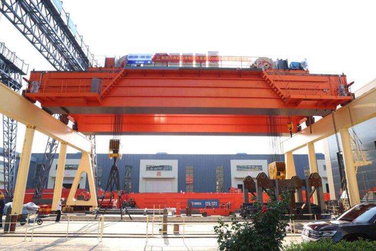
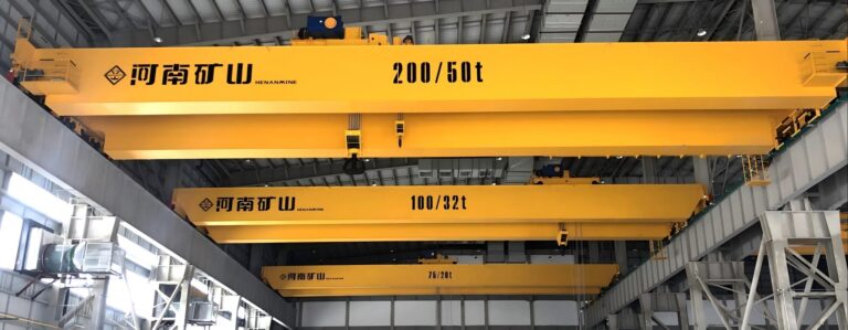
| Top-running double-girder crane | The trolley and hook arrangement can improve upper hook geometry in some applications, while bridge and platform height affect roof clearance. | Trolley structure, cab and service platforms influence transverse approach. | Evaluate for higher capacities, demanding duty and process-critical coverage. |
| Underhung crane | Suspended tracks and bridge depth must be coordinated with roof supports and the required upper hook position. | End approach may benefit in some buildings, but track support and end-truck geometry govern the result. | Use when the overhead structure can carry the system and floor columns should be avoided. |
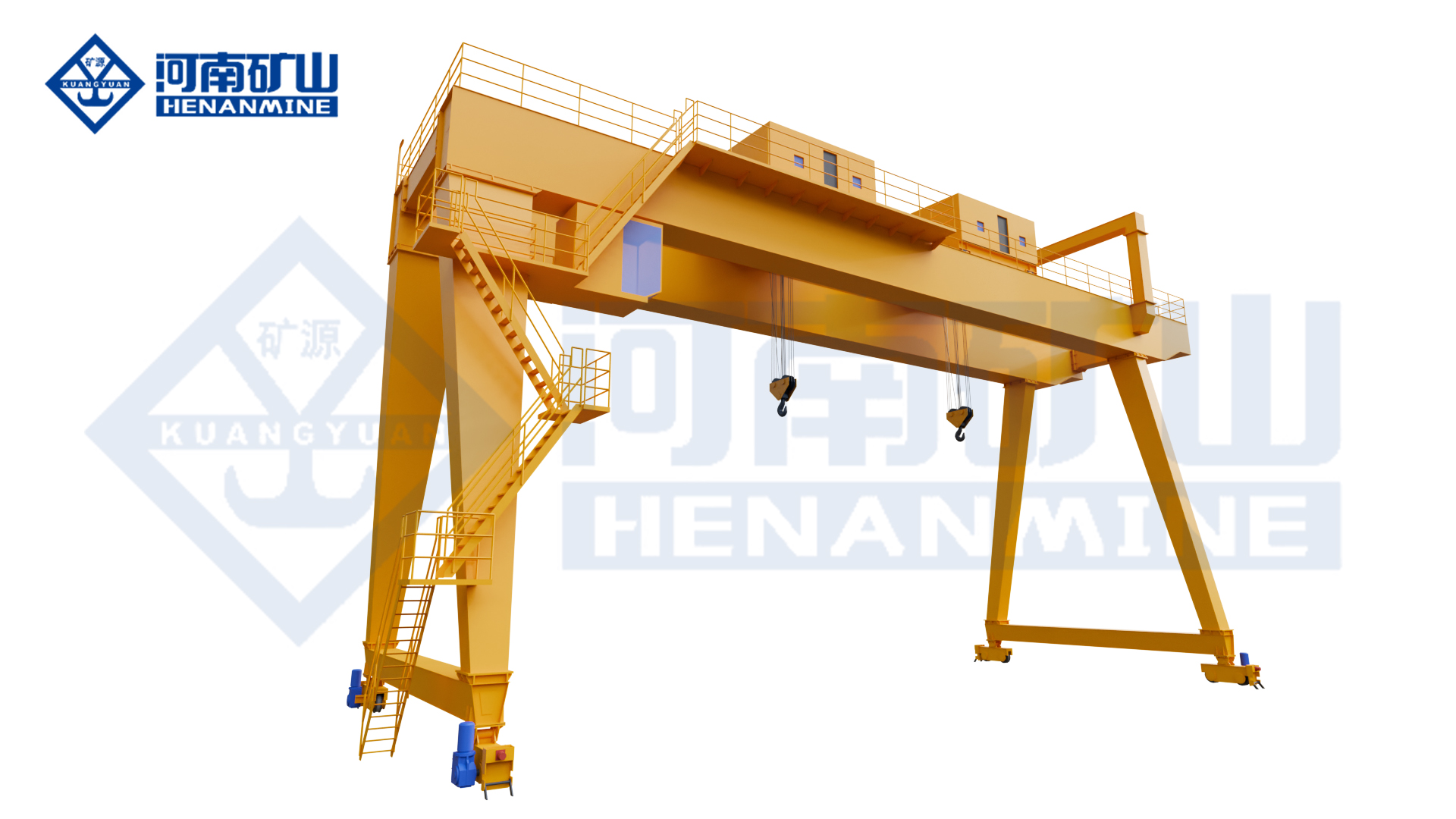
| Gantry or semi-gantry crane | Leg height, girder depth, rail/foundation elevation and cantilever geometry set the lifting envelope. | Legs, bogies, end buffers and cantilevers affect side and end coverage. | Define clear width, vehicle/load passage and hook coordinates inside and outside the legs. |

Compare the supporting architecture with the top-running vs underhung crane guide, and compare bridge/trolley geometry with the single-girder vs double-girder overhead crane guide.
5. Avoid These Costly Specification and Drawing Errors
Using Building Height as Lifting Height
Building height includes roof and structural space that the hook cannot use. Specify the upper and lower hook-center coordinates instead.
Leaving the Headroom Datum Unnamed
Rail top, beam top and beam underside produce different values. Draw the start and end points of every vertical dimension.
Providing One Hook Approach
Left, right and both runway ends can differ. Provide four limits and their exact references, plus any special process point.
Ignoring Rigging Height
Slings, spreaders and attachments can consume the vertical clearance needed to lift the load over its destination.
Measuring Only One Building Section
Roof steel and services vary along the runway. Record the lowest obstruction and support elevation at multiple stations.
Approving a Catalog Outline
Final dimensions change with capacity, span, duty, lift, trolley arrangement, cab, platforms and controls. Approve a project-specific general arrangement.
General Arrangement Approval Checklist
| Drawing Item | Required Confirmation | Buyer Acceptance Question |
|---|---|---|
| Highest hook center | Elevation and upper operating limit from the agreed datum. | Can the load and rigging reach the highest process position? |
| Lowest hook center | Elevation and lower operating limit. | Can the hook reach the floor, pit, vehicle or fixture connection? |
| Highest moving point | Crane/trolley outline, deflection considerations and required clearance. | Does the crane clear roof steel and services along the full runway? |
| Four horizontal hook limits | Left, right, end A and end B with named references. | Can the hook reach every process centerline? |
| Load/rigging envelope | Load dimensions, attachment height and any rotation/swing path. | Does the suspended load clear columns, machines, walls and gantry legs? |
| Maintenance and erection envelope | Access, removal routes, largest assembly and installation sequence. | Can the equipment be installed and serviced without unplanned building work? |
6. Site Measurement Worksheet for Crane Buyers
Record dimensions in millimeters unless the project specifies another unit. Every value should carry a drawing reference, revision, survey status and datum. Label dimensions as verified, design, provisional or supplier-required.
7. Compare Quotations Using the Same Datums and Load Case
Do not compare “12 m lift,” “1.2 m headroom” and “1.5 m approach” as isolated values. Ask every bidder to complete the same schedule and attach a drawing that uses the same building references.
| Comparison Item | Bidder A | Bidder B | Acceptance Basis |
|---|---|---|---|
| Highest hook-center elevation | Record value/datum. | Record value/datum. | Meets the governing upper process position. |
| Lowest hook-center elevation | Record value/datum. | Record value/datum. | Reaches the lowest pickup point. |
| Usable lifting height | Record operating travel. | Record operating travel. | Uses operating limits, not an undefined rope length. |
| Highest crane point / roof clearance | Record outline/clearance. | Record outline/clearance. | Clears the lowest obstruction along the runway. |
| Left/right hook approach | Record both values/references. | Record both values/references. | Reaches transverse process coordinates. |
| End A/B hook approach | Record both values/references. | Record both values/references. | Reaches longitudinal process coordinates. |
| Load/rigging clearance | State design envelope. | State design envelope. | Suspended load clears all obstacles throughout the move. |
Use the overhead crane quotation comparison guide to normalize equipment, controls, installation, documentation and commercial exclusions after the geometry has been confirmed.
8. Dimension Package to Include in the Crane RFQ
Combine these dimensions with the complete overhead crane RFQ checklist and the guide to information a crane manufacturer needs before quoting. Coordinate access, power and erection with the crane installation planning checklist.
9. Frequently Asked Questions
Is crane lifting height the same as building height?
No. Lifting height is the required vertical hook travel. Building height includes roof structure and spaces outside the usable lifting envelope.
Is headroom measured from rail top or beam underside?
Either term may appear in different product contexts. The RFQ and quotation must identify the exact reference and show the dimension on the general arrangement.
What is crane hook approach?
It normally means the horizontal distance from the hook center at a trolley or bridge travel limit to a stated side or end reference. Specify left, right and both runway ends separately.
Does a crane span equal transverse hook coverage?
No. Hook coverage is reduced by trolley geometry and travel limits. Span is based on runway support references and must be specified separately.
Can I specify only the highest hook position?
No. The manufacturer also needs the lowest hook position to select rope travel and drum arrangement, plus horizontal coordinates to confirm process coverage.
Will a low-headroom crane always provide the best hook approach?
No. Low-headroom design primarily addresses vertical geometry. Motor, drum, trolley, end carriage and building layout still determine horizontal approach.
Should hook approach be measured to the wall or rail centerline?
Use the reference that controls the process, but name it clearly. When comparing bids, every supplier must use the same reference.
What drawing should be approved before crane manufacturing?
Approve a project-specific general arrangement showing all hook limits, crane outline, roof and service clearances, support interfaces, reactions, access and installation data.
Final Recommendation
Use Hook Coordinates, Not General Terms
Specify highest and lowest hook-center elevations plus left, right and both end limits from controlled references.
Survey the Entire Crane Envelope
Record rail or beam elevations, roof structure and overhead services at every critical runway station.
Model the Suspended Load
Include load height, lifting points, rigging, attachments, rotation and clearance at each process position.
Approve One Coordinated Drawing
Release manufacturing only when the general arrangement proves vertical travel, headroom, hook coverage, building fit, maintenance access and installation feasibility.
Send Your Crane Dimensions for an Engineering Layout Review
Send Henan Mine Crane your highest and lowest hook coordinates, left/right/end approach requirements, load and rigging envelope, span, runway length, rail or beam elevations, building plan and cross-sections, capacity, duty, speeds, environment, power supply and installation access. Our technical sales and engineering teams can compare suitable crane layouts and prepare a project-specific quotation.
Request a Crane Layout and Quotation
Review Installation and Lifecycle Services