Ladle Crane Specification Guide for Molten Metal Handling
A ladle crane is a process-critical metallurgical overhead crane for lifting, transferring, pouring or charging molten metal. Buyers must define the complete suspended load, production cycle, ladle and lifting-device geometry, heat exposure, hoisting architecture, braking and limit philosophy, safety monitoring, runway reactions, maintenance access and acceptance tests before comparing quotations.
The Direct Answer: Specify the Molten-Metal Process Before the Crane
Do not buy a ladle crane as a higher-capacity version of a general-purpose overhead crane. Molten-metal service combines severe consequence of load loss, high operating duty, radiant heat, restricted process clearances and production dependence. The crane architecture and safety provisions must follow the actual steelmaking or foundry process and the governing requirements for the installation location.
For every quotation, provide one controlled process specification. It should identify the pickup point, transport route, pouring or charging point, parking position, emergency set-down area, load weights, lift cycles, thermal conditions and all operator actions. Only then can suppliers propose comparable double-girder, four-girder, main/auxiliary trolley and hoisting arrangements.
Buyer-Defined Process Inputs
- Molten-metal, ladle, attachment and hook-block weights.
- Ladle trunnion, plate-hook and tilting geometry.
- Pickup, transfer, pouring, charging and set-down coordinates.
- Cycles per hour, shifts, load spectrum and production availability.
- Ambient and radiant heat at the crane, trolley, cab and electrics.
Supplier-Defined Engineering Outputs
- Crane and mechanism classification from the stated duty.
- Bridge, trolley, hoist, rope, drum, hook and lifting-device design.
- Brake, limit, overspeed, load-monitoring and control philosophy.
- Heat protection, equipment enclosures and cooling provisions.
- Wheel reactions, clearances, maintenance access and test plan.


1. Calculate the Complete Suspended Load and Process Envelope
Rated capacity must be established from the complete lifted system under the applicable rating convention. Do not provide only molten-metal weight. Identify the maximum filled ladle, residual metal or slag condition, ladle shell and refractory, trunnion assembly, gantry or plate-hook device, hook block, equalizer elements, rigging and any process attachment carried by the crane.
| Load / Geometry Input | What the Buyer Should Provide | Why It Changes the Crane |
|---|---|---|
| Maximum suspended load | Itemized weight schedule for molten metal, ladle and all lifting equipment. | Controls rated capacity and loads in the hoist, bridge, trolley and runway. |
| Ladle and trunnions | Drawings, trunnion spacing/diameter, engagement surfaces, tolerances and center of gravity. | Determines plate-hook spacing, load sharing, clearances and pickup reliability. |
| Tilting operation | Tilting method, auxiliary-hook connection, angle, sequence, speed and load condition. | Defines main/auxiliary trolley duties, relative motion and interference checks. |
| Vertical envelope | Lowest pickup, highest hook position, pouring/charging level, ladle depth and rigging height. | Controls lifting height, headroom, rope capacity and upper/lower limits. |
| Horizontal route | Coordinates for furnace, transfer aisle, caster, pouring point, parking and emergency set-down. | Defines span, runway length, hook approaches, speeds and collision zones. |
1Approve Hook and Ladle Coordinates
The general-arrangement drawing should show the main-hook or plate-hook upper/lower limits, auxiliary-hook limits, side/end approaches, ladle outline, furnace/caster clearance, bridge depth, cab position and the lowest building obstruction. Where tilting is required, review the entire moving envelope—not only the vertical pickup position.
2Separate Main and Auxiliary Duties
For double-trolley or main/auxiliary arrangements, specify each lifting mechanism independently: rated load, load spectrum, lifting height, speed range, cycles, simultaneous-operation rules and tilting duty. Do not assume the auxiliary hook is only an occasional maintenance hoist if it participates in every pouring cycle.
2. Select Duty and Crane Architecture from the Real Load Spectrum
Crane classification should reflect total working cycles, relative frequency of different loads and motion distances over the intended design life. “Three shifts” is not enough information. Provide heats or ladle movements per day, percentage of lifts near maximum load, average travel, lift height, inching time, planned life, standby policy and expected production growth.
Henan Mine Crane product pages identify heavy metallurgical duty ranges for selected casting-crane families, but the contractual classification must be derived from the buyer’s process. An underestimated load spectrum can reduce component life; an unsupported high class can add cost without addressing the actual failure risks.
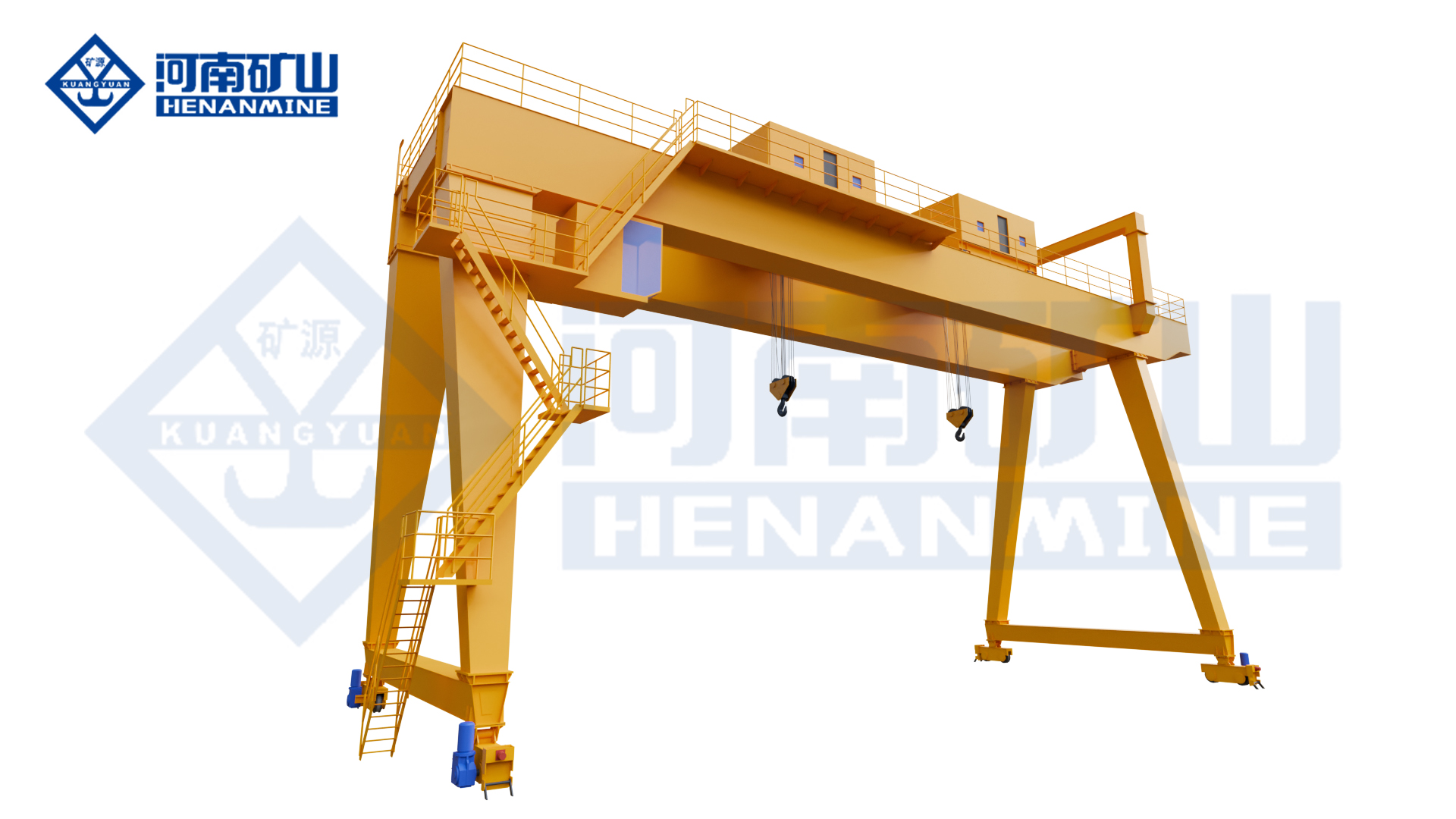
Double-Girder Casting Crane
Can be a suitable process solution where capacity, span, duty, safety basis and runway reactions support the arrangement. The main lifting device, auxiliary function and thermal protection remain purpose-designed.
Four-Girder Casting Crane
Provides a heavy metallurgical architecture with dedicated trolley rail/load paths and can support main ladle handling plus auxiliary lifting. Four- or six-rail arrangements create project-specific runway reactions.
Single-Point Metallurgical Crane
May fit defined molten-metal transfer or pouring processes using a dedicated forged hook or gantry lifting device. Its use must match the required process, load path and governing design basis.
For a broader plant-wide comparison of casting, charging, slab, coil, grab and maintenance cranes, review the steel mill overhead crane buying guide.
3. Write the Hoisting, Braking and Safety Philosophy into the Contract
Molten-metal handling requires more than a list of components. The technical agreement should explain how the load is raised, held, stopped, limited, monitored and safely recovered under defined abnormal conditions. Requirements vary by jurisdiction, owner standard, crane architecture and risk assessment; identify the governing basis instead of mixing clauses from unrelated standards.
| Safety-Critical Function | Buyer Specification Questions | Acceptance Evidence |
|---|---|---|
| Hoist drive and load path | How many motors, gear paths, drums, ropes and hook suspension points are used? What happens after each defined fault? | Design description, calculations, drawings, component certificates and functional test procedure. |
| Holding and emergency braking | What brakes act on which parts of the drive? What is their rated basis, control logic, monitoring and inspection method? | Brake data, torque-setting records, logic verification, stopping/holding tests and maintenance instructions. |
| Upper/lower travel protection | Which normal stop, final limit and overtravel protections are required, and are they suitably independent for the selected basis? | Device list, set-point schedule, circuit review and witnessed functional tests. |
| Overspeed / unintended motion | How are excessive speed, encoder disagreement, brake failure or unintended lowering detected and acted upon? | Cause-and-effect matrix, alarm/trip tests and recorded results. |
| Load measurement | Is overload prevention, load display, imbalance detection or process weighing required? What accuracy and calibration method apply? | Calibration certificates, test weights/method, alarm and interlock test. |
| Power or control loss | What state do drives, brakes, contactors and controls enter? How is a suspended ladle moved or safely set down afterward? | Failure-mode procedure, recovery logic demonstration and operator training. |
Define Permitted Simultaneous Motions
State whether hoisting, trolley travel, bridge travel and auxiliary tilting may occur simultaneously near a furnace, converter or caster. Where speed reduction, restricted zones or motion interlocks are needed, show the zones and permitted conditions on the process layout and include them in functional acceptance testing.
Specify Operator Visibility and Control
Choose cab, radio, pendant, remote station or automated control from the process risk and visibility study. Define cab position, heat exposure, air treatment, escape route, cameras, communications, alarms and emergency controls. Where remote or automated operation is requested, the buyer must provide positioning references, obstacle rules, process handshakes and a manual recovery strategy.
4. Quantify Heat Exposure and Protect Every Affected System
“High temperature” is not enough for design. Provide measured or engineered ambient temperature, radiant heat intensity or representative surface temperatures, exposure duration, distance from molten metal, hot spots along the travel route and conditions during abnormal process delays. Separate the environment at the bridge, trolley, hoist, cab, control panels, cables and runway electrification.
Control Quality Matters at the Pouring Point
Define full-speed travel and the slow-speed or creep performance needed for pickup, set-down, charging and pouring. Ask the supplier to state acceleration/deceleration control, brake sequencing, load swing strategy, encoder feedback and low-speed stability. If a precise positioning value is contractually important, specify the load condition, direction, reference point and acceptance test.
Agree on Monitoring and Data Ownership
A safety or condition-monitoring system may record loads, cycles, motor status, brake status, limits, faults, alarms and operating time. The RFQ should state which parameters are required, retention period, historian or plant-system interface, time synchronization, user access and cybersecurity requirements. Monitoring supports maintenance; it does not replace inspections or engineered protective functions.
5. Coordinate the Runway, Installation, Acceptance and Lifecycle Plan
The building and runway are part of the ladle-crane system. Heavy cranes with multiple trolley rails can produce concentrated and unequal wheel reactions that change with main/auxiliary trolley position and load combinations. The crane supplier should issue reaction schedules and locations; the responsible structural engineer should verify runway beams, rails, brackets, columns, bracing, connections and foundations.
| Project Interface | Required Procurement Output |
|---|---|
| Runway and building | Maximum/minimum wheel loads by rail, lateral/longitudinal and buffer forces, load combinations, deflection/alignment criteria and clearances. |
| Erection | Transport split, component weights, unloading, assembly area, lifting plan, temporary works, access, shutdown and heat-source isolation. |
| Factory acceptance | Document review, material/component records, dimensions, controls, limits, alarms, brake logic, monitoring and test certificates within feasible factory scope. |
| Site acceptance | Runway survey, installation inspection, no-load and load tests, all motions, limits, brakes, alarms, interlocks, emergency functions and operator training. |
| Handover | Approved drawings, calculations as contracted, certificates, test records, manuals, spare-parts list, settings, software backup and training records. |
Design Maintenance Around Production Risk
Confirm safe access to main/auxiliary hoists, brakes, drums, ropes, equalizers, hooks or plate hooks, wheel groups, controls and heat shields. Identify inspection platforms, lighting, isolation points, component-removal routes and the maximum replaceable component weight. The owner should define preventive, frequent and periodic inspection responsibilities based on applicable requirements, supplier instructions, actual duty and operating history.
Use the overhead crane preventive maintenance checklist as a planning base, then add ladle-crane-specific tasks for heat shields, ropes, drums, brakes, limits, lifting devices, load monitoring and safety functions.
Buyer Decision Matrix: What Drives the Ladle Crane Configuration?
| Process Condition | Configuration Question | Evidence to Request |
|---|---|---|
| Main transfer only | Can a purpose-designed single-point or double-girder metallurgical crane meet the risk and duty basis? | Load-path description, duty calculation, safety functions and process drawing. |
| Transfer plus frequent tilting | Are independent main and auxiliary trolleys/hooks required for the complete cycle? | Tilting sequence, simultaneous-motion rules, interference study and cycle simulation. |
| Very high capacity or severe duty | Does a four-girder/four- or six-rail architecture better distribute the required trolley and bridge loads? | Structural calculations, wheel reactions, runway layout and maintenance plan. |
| High radiant heat | What shields, insulation, cable routing, cooling and equipment derating are needed? | Thermal input map, material/component ratings and protection layout. |
| Production cannot tolerate long outages | Which redundancies, diagnostics, service access and stocked spares reduce recovery time? | Failure/recovery analysis, critical-spares list, removal route and service response. |
Ladle Crane RFQ Checklist
Send the same data package to every bidder and require every exclusion or assumption to be stated. This prevents a low bid from hiding a lighter duty basis, incomplete heat protection or missing site scope.
Use the complete overhead crane RFQ checklist and the guide to information a crane manufacturer needs before quoting to organize the enquiry package.
Relevant Henan Mine Crane Products and Project References
YZS Four-Girder Casting Crane
Four-girder, four- or six-rail, double-trolley metallurgical platform for main ladle handling, tilting and auxiliary lifting, configured to the project.
YZ Double-Girder Casting Crane
Purpose-designed double-girder casting crane for molten-metal transfer, pouring or charging where its capacity, duty and risk basis fit the process.
YZD Metallurgical Overhead Crane
Single-lifting-point metallurgical crane for defined molten-metal transfer and pouring applications using a dedicated lifting device.

Review the 200t four-girder casting-crane project, 360t heavy-duty casting-crane project and 450t four-girder casting-crane project for related application references. Project examples demonstrate capability; they do not replace a new project specification.
Frequently Asked Questions
How should ladle-crane capacity be calculated?
Start with the maximum complete suspended load under the applicable rating basis: molten metal, filled ladle, refractory, trunnions, gantry or plate-hook device, hook block, equalizing components and required rigging. State each weight separately.
Does every ladle crane need four girders?
No. Bridge architecture depends on capacity, span, duty, trolley arrangement, load path, safety basis, runway capacity and applicable requirements. Double-girder and four-girder solutions serve different project conditions.
Why is the load spectrum more important than shift hours?
Component fatigue and mechanism classification depend on how often different loads are lifted and how far each motion travels. Two three-shift plants can impose very different crane duty.
What heat information does the manufacturer need?
Provide ambient and radiant conditions at the bridge, trolley, hoist, cab, controls and cables, plus duration, route hot spots and abnormal waiting conditions. Actual thermal exposure controls material, shielding, cooling and component selection.
Should the main and auxiliary hoists have separate duty ratings?
Yes. Define each mechanism from its actual load spectrum and cycles. If the auxiliary hook participates in regular ladle tilting, its duty should reflect that process rather than occasional maintenance use.
What wheel-load information should be requested?
Request maximum and minimum reactions for each wheel/rail under governing trolley and load positions, plus lateral, longitudinal, impact/dynamic and buffer forces, load combinations and reaction locations.
Can a ladle crane be automated?
Automation can be considered where the process, positioning references, obstacle control, plant communication, safe states and recovery procedures are fully defined. The acceptance plan must test normal, degraded and emergency modes.
What should be witnessed during final acceptance?
Witness the agreed no-load/load tests, motions, speeds, brakes, limits, load monitoring, alarms, interlocks, emergency functions, main/auxiliary logic, control interfaces and documentation handover using approved procedures.
Final Recommendation
Freeze the Process and Risk Basis First
Define the complete load, ladle geometry, transfer/tilting cycle, thermal map, safety basis, abnormal conditions and required production availability before selecting bridge or hoist architecture.
Compare Testable Technical Proposals
Require bidders to state classification, load path, main/auxiliary duties, braking and limits, heat protection, monitoring, wheel reactions, maintenance access, exclusions and acceptance evidence.
Award on Lifecycle Risk—not Lowest Equipment Price
Evaluate crane, runway/building work, installation, testing, spares, maintenance labor, outage exposure, service support and future modernization as one commercial decision.
Request a Project-Specific Ladle Crane Proposal
Send Henan Mine Crane your molten-metal and ladle weights, trunnion/attachment drawings, process route, span, lifting height, runway length, cycle data, thermal conditions, building drawings, control requirements and destination. Our technical sales and engineering teams can review missing inputs and propose a suitable metallurgical crane configuration.