MDG L-Type Gantry Crane
For yards and ports handling long loads or loads that must rotate through the leg area, where L-shaped legs provide more usable passage than a conventional closed leg layout.

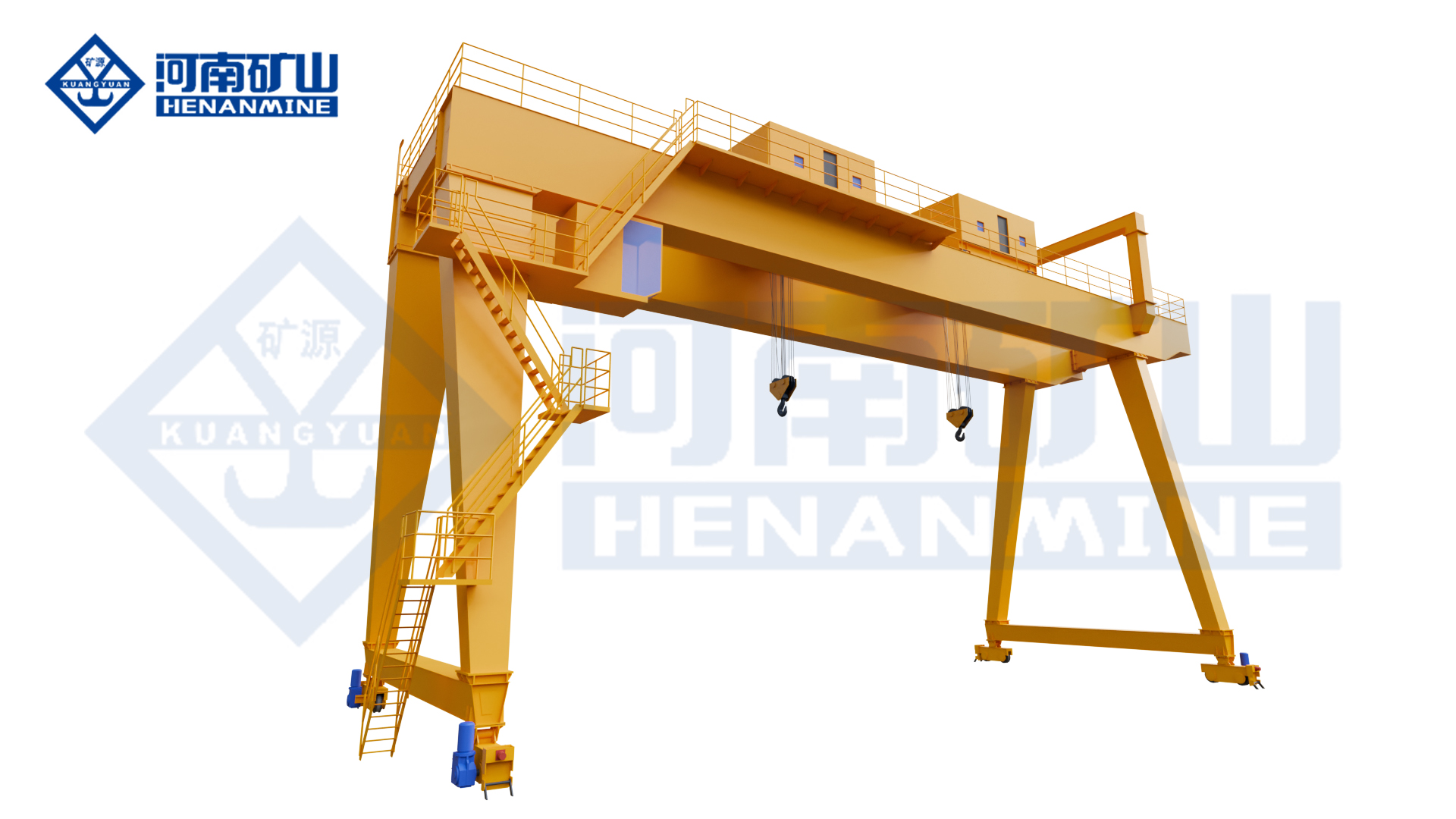
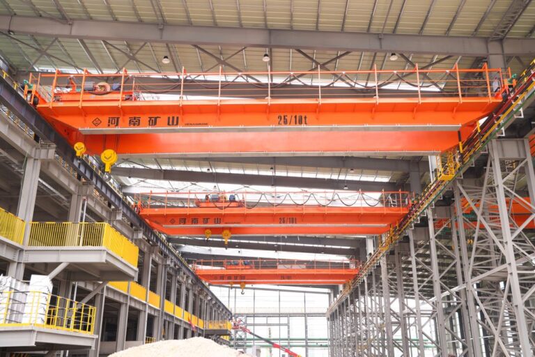
Henan Mine Crane mdg l-type gantry crane showing the primary gantry structure and lifting arrangement.
The MDG L-type gantry crane is a single-main-girder gantry crane with a winch hoisting mechanism and L-shaped legs. The source publishes rated capacity of 5–50 t and span of 18–35 m for the product family and positions it for outdoor loading and unloading in yards and ports.
For procurement, the buyer should start with the load length and turning envelope. L-type geometry is most valuable when the suspended load must pass the legs or rotate at a large angle. Cantilever coverage, runway length and outdoor wind conditions then determine the practical yard layout.
Quick Specifications
| Product Model |
MDG |
| Type-Test Product Name |
General Gantry Crane |
| Lifting Capacity |
Source-stated where published; otherwise project-specific |
| Span |
Source-stated where published; otherwise project-specific |
| Lifting Height |
Project-specific unless source-stated |
| Runway / Travel Length |
Project-specific |
| Working Duty |
Source-stated where published; otherwise selected from actual duty |
| Lifting Attachment |
According to the product and load |
| Control Method |
Source-supported options + project requirements |
| Operating Environment |
According to actual site conditions |
Best For: For yards and ports handling long loads or loads that must rotate through the leg area, where L-shaped legs provide more usable passage than a conventional closed leg layout.
Request A MDG L-Type Gantry Crane Quote
Product Overview
Single-main-girder structure with L-shaped legs.
Winch hoisting mechanism.
Source-rated capacity 5–50 t.
Any capacity, span, speed, synchronization accuracy, wind limit, temperature limit, throughput or other contractual value that is not explicitly published by the source should be engineered from the actual project and written into the technical agreement.
Why Choose MDG L-Type Gantry Crane?
Better Long-Load Clearance
L-shaped legs reduce obstruction when beams, pipes or fabricated structures pass the gantry legs.
Published Capacity / Span Range
The source provides 5–50 t and 18–35 m for this product family.
Winch Hoisting
Suitable where a winch-based lifting system is preferred over an electric-hoist arrangement.
Flexible Operator Control
Ground, remote and cabin modes are source-listed.
Smooth Gantry Travel
Three-in-one VFD travel supports smoother start/stop behavior.
Product Images

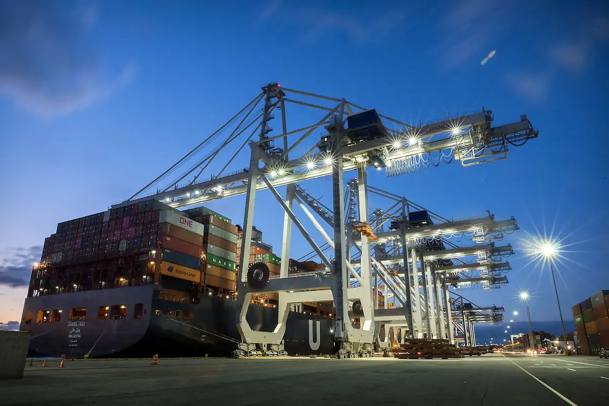
Official source image associated with the gantry crane structure or industrial application.
|

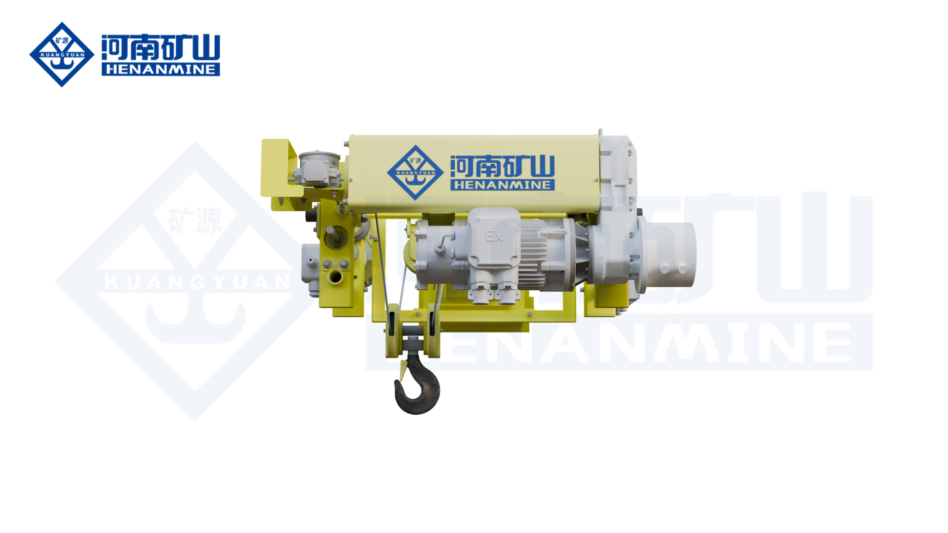
Official source image associated with the gantry crane structure or industrial application.
|
Main Crane Components
| Gantry Structure |
Main girder(s), legs and end structures selected from the exact product layout, load, span and site conditions. |
| Hoisting / Trolley System |
Configured around the product's source-described lifting mechanism and operating cycle. |
| Lifting Attachment |
Hook, grab, magnet, gantry hook, gate lifting device or construction attachment according to the product. |
| Gantry Travel System |
Moves the crane along the fixed ground rail or semi-gantry runway. |
| Electrical & Control System |
Configured from source-supported controls and project-specific safety / automation requirements. |
Technical Parameters
| Model |
MDG |
| Product Type |
MDG L-Type Gantry Crane |
| Type-Test Product Name |
General Gantry Crane |
| Capacity |
Project-specific unless source-stated |
| Span |
Project-specific unless source-stated |
| Lifting Height |
Project-specific unless source-stated |
| Runway Length |
Project-specific |
| Hoisting Speed |
Project-specific |
| Trolley Travel Speed |
Project-specific |
| Gantry Travel Speed |
Project-specific |
| Working Duty |
Project-specific unless source-stated |
| Control Method |
Project-specific |
| Power Supply |
According to site electrical conditions |
| Site Environment |
According to wind, rain, dust, corrosion and temperature |
Source-Confirmed Features & Buyer-Defined Options
Source-confirmed product facts:
- Single-main-girder structure with L-shaped legs.
- Winch hoisting mechanism.
- Source-rated capacity 5–50 t.
- Source span 18–35 m.
- Ground, remote and cabin control are source-listed.
- Cable and conductor-line power supply are source-listed.
- L-shaped legs provide larger handling space and better passage for long or rotating loads.
- Gantry travel uses a three-in-one variable-frequency drive.
Buyer-defined items:
- Maximum suspended load including attachment
- Span / lifting height / runway length
- Load geometry and lifting points
- Operating frequency and duty
- Outdoor / process environment
- Control, safety and automation scope
- Rail / foundation or building-runway interface
- Installation and commissioning scope
Application Scenarios
| Ports |
Outdoor loading and unloading of long or general cargo. |
| Freight Yards |
Rail-mounted material transfer. |
| Steel / Fabrication Yards |
Long components requiring good leg clearance. |
| Construction Storage |
Outdoor handling of large fabricated items. |
How to Select the Right MDG L-Type Gantry Crane
1. Provide Load Length and Width
The largest load envelope determines whether the L-leg layout is justified.
2. Define Rotation Requirement
Show the load orientation at pickup, travel and set-down.
3. Confirm Source Range Fit
If the required capacity or span is outside 5–50 t / 18–35 m, request a project-specific review.
4. Define Cantilever / Outside Reach
State any truck or storage position beyond the rail line.
5. Define Outdoor Conditions
Provide wind, rain, temperature and corrosion conditions.
L-Type Layout: What Buyers Should Check
| Load Passage |
Check the longest load against both leg clearances. |
| Rotation Envelope |
Include the full swing radius when the load turns. |
| Source Capacity |
5–50 t. |
| Source Span |
18–35 m. |
| Travel Drive |
Three-in-one VFD drive is source-confirmed. |
Safety & Control: What Buyers Should Confirm
• Rated capacity / overload protection and attachment weight
• Upper / lower hoisting limits and trolley / gantry travel limits
• Brake and emergency-stop requirements
• Rail-end stops, buffers, anti-collision and wind protection where applicable
• Attachment-specific safety: grab, magnet, metallurgical, gate, tipping or multi-trolley functions
• Operator visibility, remote-control or camera requirements
• Automation / linked-crane fallback and recovery procedures where applicable
• Factory and site load / functional acceptance tests
Installation & Maintenance
Before manufacture, confirm rail center distance, runway length, rail elevation, foundation or building-runway capacity, available lifting height, process clearances, power supply and erection access. Outdoor projects should include wind, rain, temperature, corrosion and anchoring conditions.
Maintenance should follow the final supplied crane manual and actual duty. In addition to hoisting, brakes, ropes, wheels, drives, rails, limits and electrical systems, inspect product-specific devices such as grabs, magnets, gantry hooks, gate equipment, tipping mechanisms, encoders, cameras or automation hardware.
What Information Do We Need for a Quote?
| 1 |
Maximum suspended load |
| 2 |
Load dimensions / turning envelope |
| 3 |
Span |
| 4 |
Lifting height |
| 5 |
Runway length |
| 6 |
Cantilever length if required |
| 7 |
Outdoor wind / corrosion |
| 8 |
Operating duty |
| 9 |
Control method |
| 10 |
Power supply method |
| 11 |
Rail / foundation drawing |
| 12 |
Destination / installation scope |
Frequently Asked Questions
How is final crane capacity selected?
Use the complete suspended load, including the load plus grab, magnet, gantry hook, lifting beam, rigging or any other below-the-hook equipment.
Can span and lifting height be customized?
Yes. Unless the source publishes a range, these are project-specific and should be selected from the rail layout and working envelope.
What site drawing should I send?
Send a plan and cross-section showing rails, foundations or building runway, loading positions, obstacles, travel length and available clearances.
Can control or automation be customized?
Where the source supports VFD, PLC, linked operation, cameras, access control or other functions, the final scope should be defined from the buyer's process and acceptance requirements.
How should source-reported performance numbers be used?
Treat them as source product data. If a value is contract-critical for a new project, define the test conditions and acceptance method in the technical agreement.
Related Gantry Crane Products
MEH Double-Trolley Truss Gantry Crane
MN Grab & Hook Dual-Purpose Gantry Crane
MEN Double-Trolley Electromagnetic & Hook Gantry Crane
MGBE Double-Trolley Semi-Gantry Crane
MC Electromagnetic Gantry Crane
MDE Double-Trolley L-Type Gantry Crane
Request A MDG L-Type Gantry Crane Quote
Send your maximum load, span, lifting height, runway length, site drawing, operating cycle, load geometry, lifting attachment and special control / environment requirements. Henan Mine Crane engineers can then review the actual process and prepare a project-specific configuration and quotation.
Request A Quote | View Gantry Cranes