QE Double-Trolley Hook Overhead Crane
For buyers who need two hook trolleys on one bridge for independent jobs, long-load tandem lifts or flexible multi-point handling.

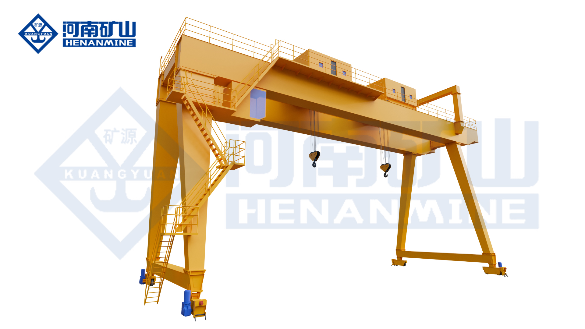
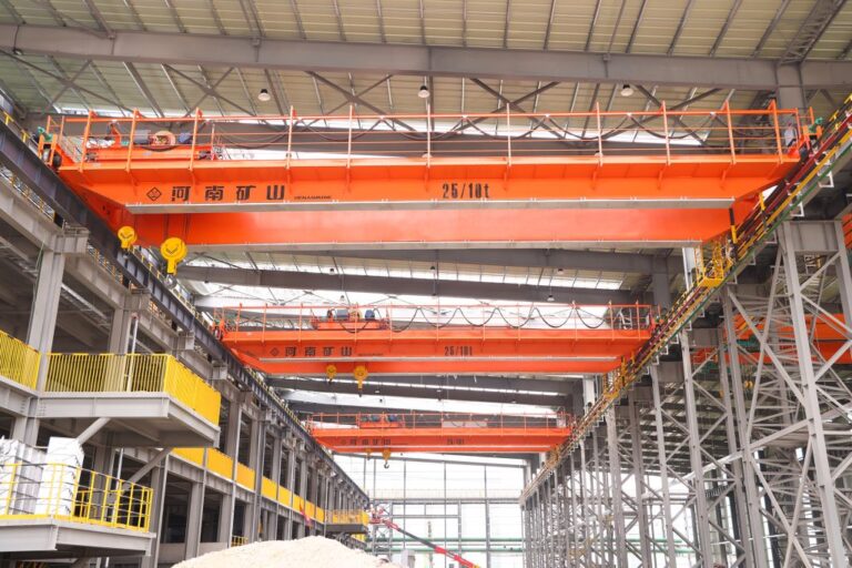
Henan Mine Crane qe double-trolley hook crane showing the primary crane structure and lifting arrangement.
The QE double-trolley hook overhead crane uses two trolley lifting systems on one general bridge crane. The source states that the trolleys can lift together or work separately and lists working classes A1–A8 for the product family.
For procurement, the most important data are not only total capacity but also maximum load per trolley, load length, center of gravity, lifting-point spacing and the permitted height difference during tandem operation.
Quick Specifications
| Product Model |
QE |
| Type-Test Product Name |
General Overhead Crane |
| Lifting Capacity |
Configured according to project requirements |
| Span |
Configured according to runway center distance |
| Lifting Height |
Configured according to workshop / process requirements |
| Working Duty |
Configured from source data and actual load spectrum |
| Lifting Attachment |
Configured according to the product and load |
| Control Method |
Configured according to project requirements |
| Source-Stated Working Class |
A1–A8 |
| Source-Stated Wheel-Life Improvement |
About 20% vs traditional forged-wheel process (source claim) |
Best For: For buyers who need two hook trolleys on one bridge for independent jobs, long-load tandem lifts or flexible multi-point handling.
Request A QE Double-Trolley Hook Crane Quote
Product Overview
General bridge crane with two trolleys that can lift together or operate independently.
Source lists working class A1–A8.
Multiple control combinations are available according to the source.
Where the source page does not publish a numerical capacity, span, speed, duty, positioning accuracy or other guaranteed performance value, the final value should be selected and agreed from the actual project rather than copied from a similar crane.
Why Choose QE Double-Trolley Hook Crane?
Independent or Tandem Use
One crane supports separate trolley work and combined long-load lifting.
Encoder / Inverter Coordination
Source-listed double-trolley control technology supports coordinated operation.
Broad Duty Selection
Source lists A1–A8, allowing the final design to be matched to actual usage rather than one fixed duty.
Flexible Control
Multiple control combinations can be configured.
Long-Load Handling
Two lifting points improve control of long or large structures.
Product Images

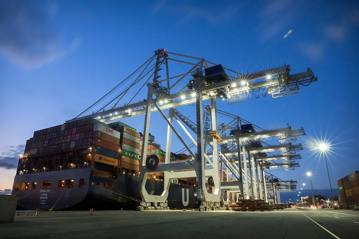
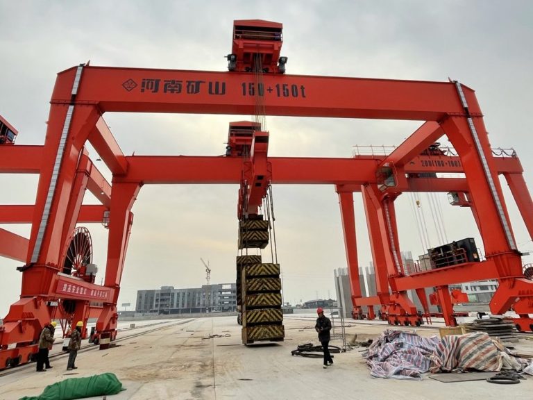
Source image associated with the QE Double-Trolley Hook Crane, showing the multi-trolley crane or an industrial application.
|

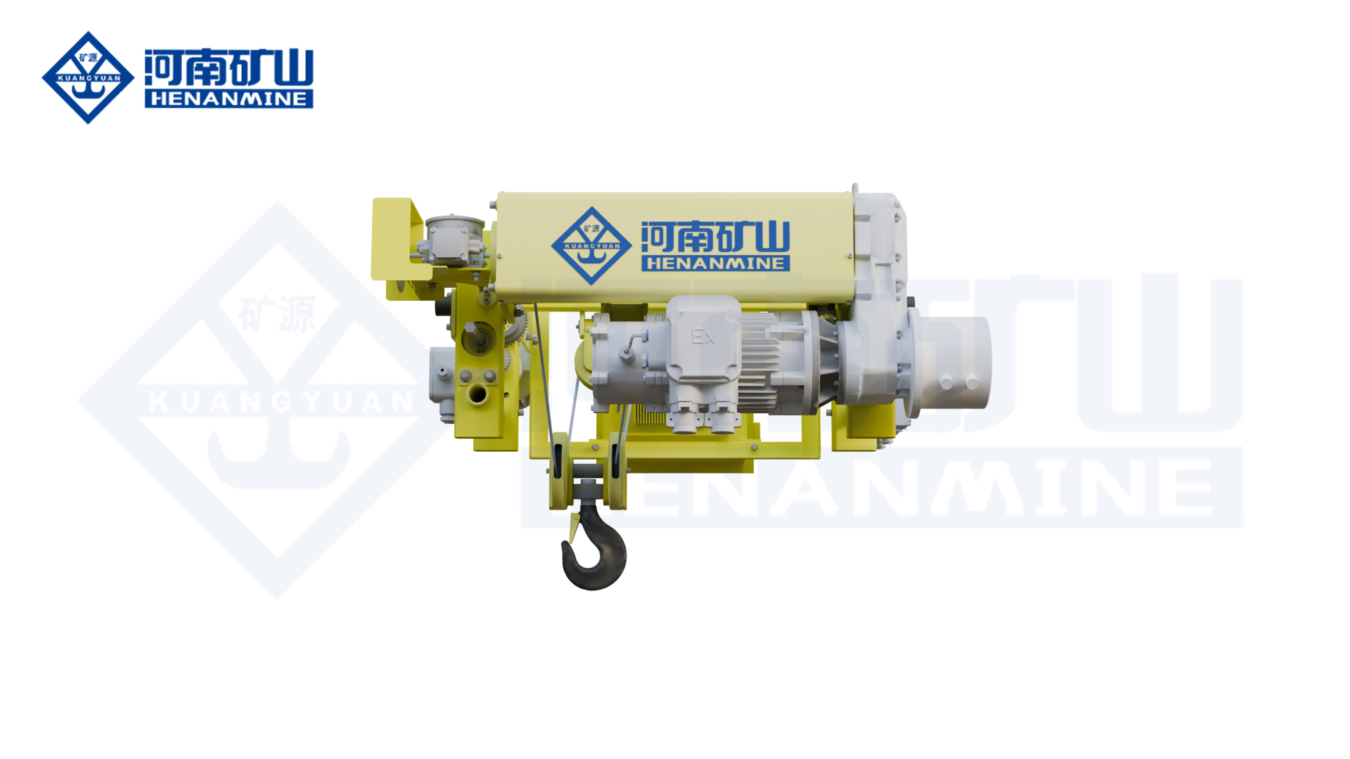
Source image associated with the QE Double-Trolley Hook Crane, showing the multi-trolley crane or an industrial application.
|

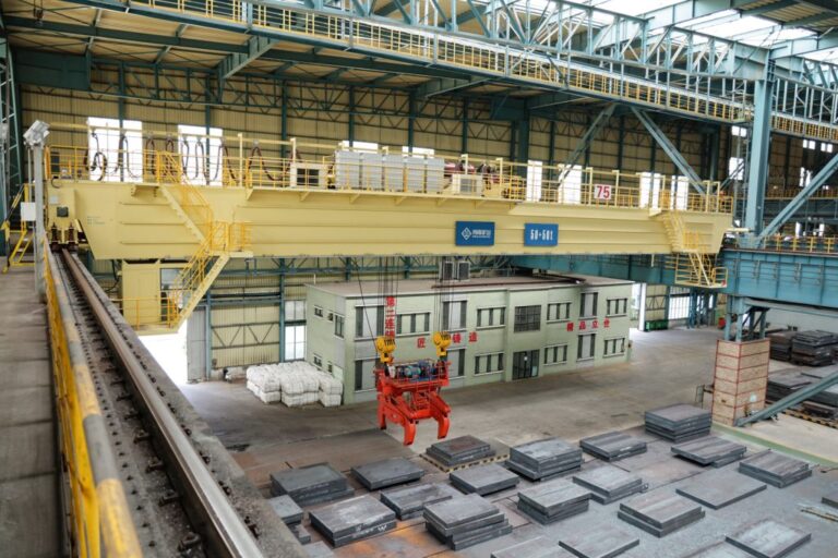
Source image associated with the QE Double-Trolley Hook Crane, showing the multi-trolley crane or an industrial application.
|

Source image associated with the QE Double-Trolley Hook Crane, showing the multi-trolley crane or an industrial application.
|

Source image associated with the QE Double-Trolley Hook Crane, showing the multi-trolley crane or an industrial application.
|

Source image associated with the QE Double-Trolley Hook Crane, showing the multi-trolley crane or an industrial application.
|
Main Crane Components
| Bridge Structure |
Engineered from capacity, span, duty, runway and product-specific process loads. |
| Hoisting / Trolley System |
Configured for the product's lifting mechanism and operating cycle. |
| Lifting Attachment |
Selected from the actual load geometry, material and process. |
| Travel System |
Bridge and trolley travel selected for required speed, duty and positioning. |
| Electrical & Control System |
Configured for operator control, safety functions and any source-supported automation / monitoring. |
Technical Parameters
| Model |
QE |
| Product Type |
QE Double-Trolley Hook Overhead Crane |
| Type-Test Product Name |
General Overhead Crane |
| Capacity |
Project-specific unless source-stated above |
| Span |
Project-specific unless source-stated above |
| Lifting Height |
Project-specific |
| Hoisting Speed |
Project-specific |
| Trolley / Crane Travel Speed |
Project-specific |
| Working Duty |
Project-specific unless source-stated above |
| Control Method |
Project-specific |
| Power Supply |
According to site electrical conditions |
| Operating Environment |
According to actual process conditions |
Source-Confirmed Features & Buyer-Defined Options
Source-confirmed product facts:
- General bridge crane with two trolleys that can lift together or operate independently.
- Source lists working class A1–A8.
- Multiple control combinations are available according to the source.
- Double-trolley control uses encoders and CI-card inverter technology.
- Source reports forged/rolled composite wheel process with about 20% longer life than traditional forged-wheel process.
Buyer-defined items:
- Capacity and total suspended load
- Span / lifting height / runway length
- Load geometry and lifting attachment
- Operating frequency and working duty
- Control and safety functions
- Positioning / synchronization / automation where applicable
- Installation, testing and commissioning scope
Application Scenarios
| Long Components |
Tandem lifting of beams, equipment and fabricated structures. |
| Assembly Bays |
Two-point positioning of large modules. |
| General Manufacturing |
Independent trolley handling in one bay. |
| Maintenance |
Coordinated lifts for equipment removal / installation. |
How to Select the Right QE Double-Trolley Hook Crane
1. Provide Total and Per-Trolley Load
Center of gravity can make trolley loads unequal.
2. Provide Lifting-Point Spacing
Defines trolley travel range during tandem work.
3. Define Synchronization Requirement
State allowable hook-height difference or load tilt.
4. Define Independent Duties
Provide the maximum load each trolley handles alone.
5. Select Working Duty
Use actual cycles and load spectrum rather than defaulting to a high class.
Double-Trolley RFQ Check
| Per-Trolley Capacity |
Do not assume the total crane capacity is equally shared. |
| Load Geometry |
Center of gravity determines actual hook reactions. |
| Synchronization |
Define allowable height difference / tilt and acceptance method. |
| Control Combinations |
State whether separate operators or one coordinated control station are required. |
Safety & Control: What Buyers Should Confirm
• Rated capacity, overload protection and load-indication requirements
• Hoisting / travel limits, braking and emergency-stop requirements
• Attachment-specific safety such as magnet backup, grab interlocks, clamps or tandem synchronization where applicable
• Operator control method, visibility and safe access
• Anti-collision, anti-sway, positioning or automation requirements where required by the process
• Factory / site acceptance, load tests and project-specific functional tests
Installation & Maintenance
Before manufacture and installation, confirm runway span, rail / runway-beam condition, elevation, straightness, available headroom, power supply and erection access. Special attachments, multi-trolley systems, cantilevers, suspended runways and automated layouts should be coordinated with the workshop or yard drawing before production.
Maintenance should follow the supplied crane manual and actual duty. Inspection normally covers the hoisting mechanism, brakes, ropes, hooks / attachments, wheels, drives, fasteners, limits and electrical systems, with additional checks for magnets, grabs, clamps, sensors, encoders or automation hardware where fitted.
What Information Do We Need for a Quote?
| 1 |
Total maximum load |
| 2 |
Maximum load per trolley |
| 3 |
Load dimensions / center of gravity |
| 4 |
Lifting-point spacing |
| 5 |
Synchronization / allowable tilt |
| 6 |
Span |
| 7 |
Lifting height |
| 8 |
Runway length |
| 9 |
Duty / cycles |
| 10 |
Control mode |
| 11 |
Workshop drawing |
| 12 |
Power supply and destination |
Frequently Asked Questions
How is the final crane capacity selected?
Use the total suspended load, including the load itself plus any beam, grab, magnet, clamp, spreader or rigging that remains below the hook.
Can the capacity, span and lifting height be customized?
Yes, these values are project-specific unless a source range is explicitly listed on this page. Provide the workshop / yard data for engineering selection.
What should I provide for a faster quotation?
Provide load drawings or dimensions, maximum suspended load, span, lifting height, runway length, operating cycle, environment and the specific process function that makes this product necessary.
Can control and automation be customized?
Where the source supports PLC, VFD, positioning, WMS/MES/DCS or remote functions, the final scope should be defined from the buyer's interface and acceptance requirements.
How should source-reported performance numbers be treated?
They describe the source product configuration. Any value that matters contractually for a new project should be written into the technical agreement and acceptance plan.
Related General Overhead Cranes
QLC Lower-Rotating Electromagnetic Beam Overhead Crane
QJ Lower-Rotating Beam Overhead Crane
QZ Intelligent Grab Bucket Double-Girder Overhead Crane
QEN Grab & Hook Dual-Purpose Overhead Crane
QDXG Zinc Pot Maintenance Overhead Crane
Request A QE Double-Trolley Hook Crane Quote
Send your lifting load, span, lifting height, runway length, workshop or yard drawing, operating cycle, load geometry and special attachment / control requirements. Henan Mine Crane engineers will review the process and prepare a project-specific crane configuration and quotation.
Request A Quote | View Overhead Cranes