Building Straddle Carrier
For modular-building factories that need to lift complete housing modules, move them through constrained production routes and position them for storage or truck loading without a fixed rail runway.

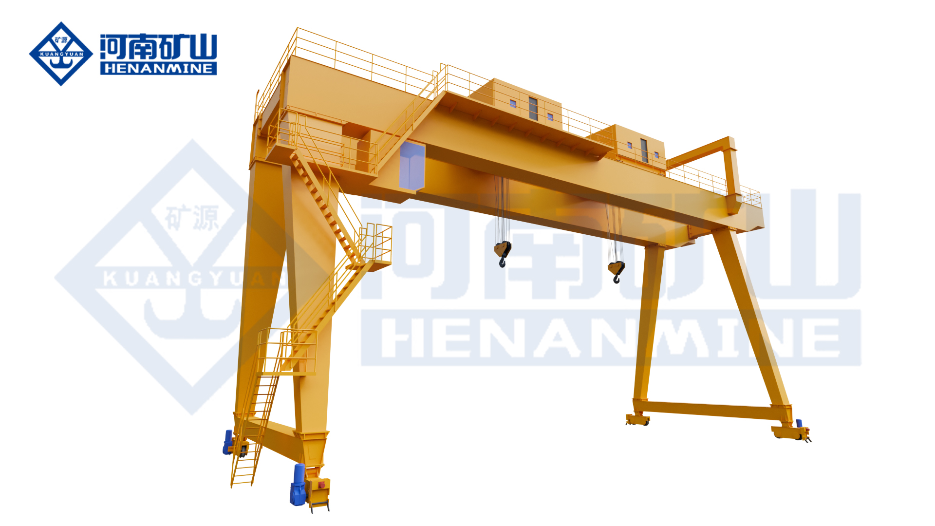
Henan Mine Crane source image for the Building Straddle Carrier, used to illustrate the product category and intended material-handling application.
Building Straddle Carrier for modular construction plants— lift, move and load housing modules in space-limited factories.
This page is written from a procurement perspective. The accessible source category identifies the product and its target application, but it does not publish one universal capacity, overall dimension, travel speed, turning radius, tire load, gradeability or power system for this exact product. Those items are therefore treated as project-specific rather than invented.
Quick Specifications
| Model / Product Family |
Straddle Carrier |
| Mobility |
Rubber-tired / straddle-carrier product family |
| Lifting Capacity |
Configured according to the complete suspended load |
| Clear Width / Span |
Configured around the load and route |
| Lifting / Under-Clearance |
Configured around pickup, transport and placement geometry |
| Travel Speed |
Project-specific |
| Turning / Steering Requirement |
Project-specific according to route geometry |
| Ground / Pavement Loading |
Project-specific; final tire / axle loads must be checked |
| Working Duty |
Selected from moves per hour, travel distance and load spectrum |
| Control / Operator Mode |
Project-specific |
| Power / Drive System |
Project-specific |
| Environment |
Configured for actual indoor / outdoor site conditions |
Best For: For modular-building factories that need to lift complete housing modules, move them through constrained production routes and position them for storage or truck loading without a fixed rail runway.
Request A Building Straddle Carrier Quote
Product Overview
Building Straddle Carrier for modular construction plants— lift, move and load housing modules in space-limited factories.
A rubber-tired lifting carrier should be selected as both a crane and a mobile transport system. The lifting arrangement must safely support the load, while the travel system must fit the real route, turning space, ground condition and production cycle. For many projects, route data is as important as capacity.
Before quotation, provide a site layout and the largest load drawing. This allows the supplier to review the load envelope, clear width, lifting height, turning zones, surface capacity and pickup / set-down interfaces together.
Why Choose a Building Straddle Carrier?
Module-Centered Handling
The source positions this carrier specifically around complete building modules rather than general loose cargo.
No Fixed Rail Dependency
A rubber-tired / straddle approach is relevant where module flow changes between production, storage and loading areas.
Space-Limited Factory Fit
The source explicitly targets space-limited modular construction plants.
Direct Production-to-Loading Workflow
The same equipment can be engineered around pickup, internal transport and vehicle-loading positions.
Product Images
The current source category exposes one product image for this item. It is shown above as the main image and is not repeated here to avoid duplicate media on the final product page.
Main Equipment Systems
| Load-Bearing Gantry / Carrier Structure |
Configured around the exact product form, load envelope and required clear width. |
| Hoisting / Lifting System |
Selected from suspended load, lifting points, lifting height and duty. |
| Load Attachment / Spreader |
Project-specific and selected for the actual load geometry and lifting rules. |
| Rubber-Tired Travel System |
Configured around loaded travel, route geometry and pavement conditions. |
| Steering / Maneuvering System |
Project-specific; selected from turning-space and route requirements. |
| Brake / Parking System |
To be specified according to loaded travel, slope, parking and site safety requirements. |
| Electrical / Hydraulic / Drive System |
Power architecture is project-specific unless confirmed in the final technical proposal. |
| Operator / Control System |
Configured according to visibility, travel route and project operating concept. |
Technical Parameters
| Product |
Building Straddle Carrier |
| Model / Family |
Straddle Carrier |
| Rated Capacity |
Project-specific |
| Clear Width / Span |
Project-specific |
| Lifting Height / Under-Clearance |
Project-specific |
| Overall Width / Height |
Project-specific |
| Travel Speed |
Project-specific |
| Turning Radius / Steering Geometry |
Project-specific |
| Grade / Slope Requirement |
Project-specific |
| Tire / Wheel Load |
Project-specific |
| Working Duty |
Project-specific |
| Attachment / Spreader |
Project-specific |
| Control Mode |
Project-specific |
| Power / Drive |
Project-specific |
| Outdoor Wind / Corrosion |
Project-specific where applicable |
Source-Confirmed Facts & Buyer-Defined Options
Source-confirmed facts:
- Product name: Building Straddle Carrier.
- Category model / family: Straddle Carrier.
- Source application statement: Building Straddle Carrier for modular construction plants— lift, move and load housing modules in space-limited factories.
Buyer-defined items:
- Maximum load and load envelope
- Center of gravity and lifting points
- Required attachment / spreader
- Clear width and lifting / under-clearance
- Travel route and turning space
- Ground / pavement bearing conditions
- Moves per hour / shift
- Steering / control / power concept
- Outdoor wind / corrosion if applicable
- Commissioning and operator-training scope
Application Scenarios
| Modular Housing Plants |
Move finished room or building modules between production stations. |
| Module Storage Yards |
Reposition finished modules without a fixed crane runway. |
| Truck Loading Areas |
Transfer modules from storage / assembly positions to transport vehicles. |
| Factory Logistics |
Move oversized modules through constrained internal routes. |
How to Select the Right Building Straddle Carrier
1. Provide the Largest Module Envelope
Length, width and height determine clear width, lifting height and passage requirements.
2. Provide Module Weight and Center of Gravity
Include any lifting frame or spreader in the total suspended load.
3. Define Lifting Points
Provide lifting-lug coordinates and allowable lifting reactions from the module designer.
4. Map the Travel Route
Show aisle widths, door openings, turning areas, overhead obstructions and truck-loading positions.
5. Check Floor / Yard Capacity
Provide pavement or floor bearing information for the loaded travel route.
6. Define Daily Flow
Modules per shift and travel distance determine duty and productivity requirements.
Modular Building Handling Data Buyers Must Provide
| Module Dimensions |
Maximum L × W × H for every module family. |
| Center of Gravity |
Needed for stable lifting and attachment design. |
| Lifting Points |
Coordinates and allowable forces from the module structure. |
| Minimum Passage |
Door, aisle and turning-space constraints. |
| Loading Interface |
Truck / trailer deck height and approach position. |
| Production Throughput |
Modules per shift and typical travel distance. |
Rubber-Tired Travel: What Buyers Should Confirm
| Travel Route |
Provide the full loaded route, not only pickup and set-down points. |
| Minimum Width |
Measure the tightest aisle, gate, lane or crossing. |
| Turning Space |
Show corners, intersections and required reversing / maneuvering zones. |
| Slope / Cross-Fall |
Provide route grades where the carrier will travel loaded. |
| Surface Capacity |
Provide pavement, slab or ground bearing information. |
| Surface Condition |
Identify joints, potholes, rails, drains or transitions that affect tire travel. |
| Travel Frequency |
Moves per hour / shift and loaded distance affect duty and maintenance. |
| Parking Area |
Define safe parking / maintenance location and any outdoor wind requirement. |
Safety & Control: What Buyers Should Confirm
• Rated capacity / overload protection and lifting-attachment weight
• Load stability throughout lift, travel, turning and placement
• Hoisting limits and emergency-stop requirements
• Travel braking, parking and slope-holding requirements
• Steering / maneuvering visibility and operator warning requirements
• Tire condition, wheel / axle load and pavement compatibility
• Anti-collision / obstacle detection if required by the route
• Outdoor wind / parking protection where applicable
• Factory and site load / travel / braking / turning acceptance tests
Installation, Commissioning & Maintenance
Before manufacture, freeze the load drawing, lifting points, route layout, minimum clearances, ground conditions, pickup / set-down positions and operating cycle. Because the equipment is mobile, site acceptance should verify not only lifting but also loaded travel, steering, braking and placement on the actual route.
Maintenance planning should cover the hoisting system, ropes / chains where fitted, attachment, brakes, tires, wheel / axle assemblies, steering components, drive system, structural connections, controls and safety devices. High-frequency applications should define inspection access and spare-part strategy before purchase.
What Information Do We Need for a Quote?
| 1 |
Maximum module weight |
| 2 |
Maximum module dimensions |
| 3 |
Center of gravity |
| 4 |
Lifting-point drawing |
| 5 |
Required lifting height / under-clearance |
| 6 |
Factory aisle / door dimensions |
| 7 |
Travel distance and turning areas |
| 8 |
Floor / yard bearing information |
| 9 |
Modules per shift |
| 10 |
Control / operator preference |
| 11 |
Indoor / outdoor conditions |
| 12 |
Power / drive preference if required |
| 13 |
Factory layout |
| 14 |
Destination / commissioning scope |
Frequently Asked Questions
What determines the correct lifting capacity?
Use the complete suspended load, including the load plus spreader, lifting beam, sling or other permanent attachment.
Why do you need a site route drawing?
A rubber-tired carrier is both a lifting machine and a transport machine. Route width, turning space, slope and pavement can change the required configuration.
Can the dimensions and steering arrangement be customized?
These items are project-specific on the accessible source page. They should be engineered from the actual load and route rather than selected from an assumed standard size.
What affects price most?
Load capacity, clear width, lifting height, route / steering requirements, tire / axle loading, attachment, duty, control / power system and environmental requirements are major design drivers.
What should be tested before acceptance?
The technical agreement should define load lifting, loaded travel, steering, braking, safety functions and any placement / productivity requirements that matter to the project.
Related Rubber-Tired Gantry Products
Wind Turbine Straddle Carrier
Steel Mill Straddle Carrier
Precast Concrete Straddle Carrier
Straddle Carrier Crane
A-Frame Rubber-Tired Gantry Crane
Double Rubber-Tired Gantry Crane
Request A Building Straddle Carrier Quote
Send the maximum load, load dimensions, center of gravity, lifting points, required clearances, full travel-route drawing, ground / pavement information and handling frequency. Henan Mine Crane can then review the lifting and mobile-travel requirements together and prepare a project-specific configuration and quotation.
Request A Quote | View Gantry Cranes