Ship-to-Shore Crane (STS)
High-throughput quay crane engineered around your design vessel, container mix, outreach, lift height, quay structure and target moves per hour.
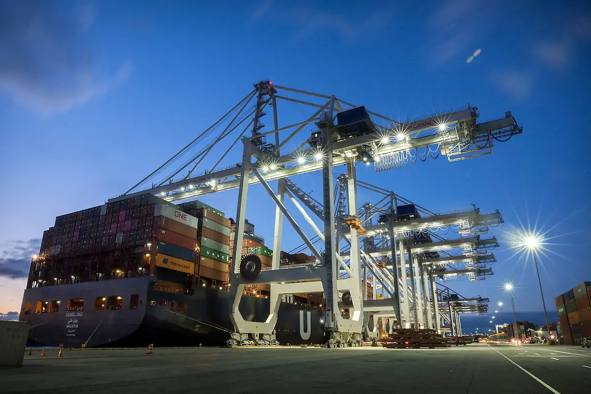
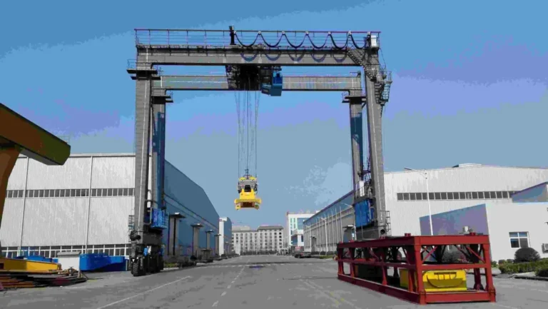
Ship-to-shore container cranes operating at a dedicated container terminal.
A ship-to-shore crane, also called an STS crane or container quay crane, transfers ISO containers between a vessel and terminal transport at the berth. Its waterside outreach, lifting height, rail gauge, load capacity and operating speeds are configured for the terminal's design vessel and productivity plan.
Henan Mine Crane supplies project-specific STS crane solutions for new container terminals, berth expansions and equipment replacement projects. The engineering process connects vessel geometry, wharf conditions, container handling mode, environmental loads and control requirements to one coordinated crane specification—helping buyers evaluate reach, throughput, infrastructure compatibility and lifecycle support before ordering.
Quick Specifications
| Product Type |
Ship-to-shore container crane / STS crane / container quay crane |
| Primary Duty |
Vessel-to-terminal and terminal-to-vessel ISO container handling |
| Design Vessel / Rows Across |
Project-specific |
| Rated Load Under Spreader |
Project-specific |
| Rated Load Under Hook |
Project-specific, when required |
| Waterside Outreach |
Project-specific, measured from the waterside crane rail reference |
| Backreach / Rail Gauge |
Project-specific |
| Lift Above / Below Rail |
Project-specific |
| Container Spreader |
Selected for the required container sizes and handling mode |
| Target Productivity |
Project-specific moves per hour and operating profile |
| Power Supply / Control Level |
Project-specific |
| Quay Loads / Environmental Design |
Verified against project rail, wharf, wind, corrosion, temperature and seismic data |
Best For
Dedicated container terminals and multipurpose ports that need efficient vessel loading and unloading, larger vessel reach, higher berth productivity, or a customized replacement crane compatible with an existing quay.
Planning a new berth or upgrading an existing container terminal?
Send your vessel, quay and productivity data for a project-specific STS crane proposal.
Request a Technical Proposal
Product Overview
The STS crane is the primary waterside handling machine in a container terminal. A rail-mounted portal structure travels along the quay while a trolley moves the spreader between the ship and landside transfer area. The hoisting, trolley and gantry systems are coordinated to shorten container transfer cycles while maintaining load control and safe clearances.
Unlike an RMG or RTG crane, which stacks and transfers containers in the yard, the STS crane is designed around the ship interface. Vessel beam, container rows across, deck stack height, hatch geometry, air draft, tidal range and fender line all influence the required outreach and lifting geometry.
For this reason, an STS crane should not be selected from capacity alone. A workable specification must also confirm rail gauge, backreach, boom parking envelope, quay wheel loads, terminal vehicle interface, wind conditions, power supply and the buyer's target berth productivity.
Why Choose a Henan Mine Crane STS Solution?
Engineered for the Design Vessel
Outreach, lift height and clearances are developed from the vessel class, container rows, hatch layout and berth geometry supplied by the buyer.
Productivity-Oriented Configuration
Hoist, trolley, gantry and control functions are selected against the target operating cycle, container mix and terminal transfer process.
Quay Interface Verification
Rail geometry, allowable wheel loads, power interface, storm securing points and maintenance access are coordinated before manufacture.
Safety and Load Control
The control architecture can integrate load monitoring, travel limits, anti-sway functions, wind protection, alarms and project-required interlocks.
Scalable Control Options
Cab operation, remote support, condition monitoring and higher automation levels can be evaluated according to terminal objectives.
Lifecycle Planning
Equipment access, inspection points, spare parts strategy, commissioning and operator training can be included in the delivery scope.
Product Image
Image use note: The current product page contains one dedicated STS crane image, shown once above at full width. It is not repeated or replaced with visually similar RMG, RTG or yard-crane images, so the page remains product-accurate.
Main Equipment Systems
| System |
Function and Selection Focus |
| Portal, Girder and Boom Structure |
Provides the structural load path and vessel reach; designed around gauge, outreach, backreach, boom clearance and environmental loads. |
| Boom Hoisting / Luffing System |
Raises or parks the waterside boom for vessel access, navigation clearance and non-operating conditions according to the selected arrangement. |
| Main Hoisting System |
Lifts the spreader and container through the specified vertical travel at project-defined load and speed. |
| Trolley Travel System |
Transfers the suspended container between vessel and landside interface; speed, acceleration and load control influence the operating cycle. |
| Container Spreader |
Interfaces with the required ISO container sizes; single, twin or other handling modes are selected only when stated in the project specification. |
| Gantry Travel System |
Moves the crane along quay rails to serve vessel bays, with travel alarms, braking and storm-security interfaces. |
| Operator Station and Visibility |
Supports safe monitoring of the vessel, load path and landside transfer zone; cabin, cameras and remote functions are project-specific. |
| Electrical and Control System |
Coordinates hoist, trolley, gantry, boom and spreader functions using the specified drives, PLC architecture, communications and diagnostics. |
| Sway, Skew and Position Control |
Assists container positioning and cycle consistency; the required functions and automation level depend on the terminal operating concept. |
| Wind and Storm Securing |
Includes project-selected wind monitoring, service braking, rail clamps, storm pins and tie-down provisions coordinated with the quay. |
Technical Parameters
STS crane dimensions and performance are finalized after the vessel, berth and operating data have been reviewed. The following schedule identifies the parameters that should appear in the technical agreement.
| Parameter |
Configuration |
| Rated Load Under Spreader |
Project-specific |
| Rated Load Under Hook |
Project-specific, if hook handling is required |
| Design Vessel / Rows Across |
Project-specific |
| Outreach from Waterside Rail |
Project-specific |
| Backreach |
Project-specific |
| Rail Gauge |
Project-specific |
| Lift Height Above Rail |
Project-specific |
| Lowering Depth Below Rail |
Project-specific |
| Hoist / Trolley / Gantry Speeds |
Project-specific, evaluated against target cycle performance |
| Boom Hoisting Time / Parking Position |
Project-specific |
| Spreader Type and Container Sizes |
Project-specific |
| Duty / Target Moves per Hour |
Project-specific |
| Maximum Wheel Load / Number of Wheels |
Project-specific and subject to quay verification |
| Power Supply and Cable Interface |
Project-specific |
| Control / Automation Level |
Project-specific |
| Wind, Temperature, Corrosion and Seismic Design |
Project-specific |
| Applicable Standards / Inspection Scope |
Defined in the contract and technical specification |
Source-Confirmed Facts & Buyer-Defined Options
Confirmed on the Current Product Page
- Product: Ship-to-Shore Crane / STS Crane.
- Designed for large container terminals.
- Supports rapid loading and unloading between container ships and the terminal.
- Intended to serve large container ships and operate across multiple container rows.
- Positioned for high-throughput, high-efficiency specialized port operations.
Defined During Project Engineering
- Rated load, spreader type and container handling mode.
- Outreach, backreach, rail gauge and lifting height.
- Speeds, duty, moves per hour and automation level.
- Wheel loads, rail interface, power supply and storm securing.
- Wind, corrosion, temperature, seismic and site conditions.
- Delivery division, erection, testing, training and spare parts.
Application Scenarios
| Terminal Scenario |
Typical Selection Priority |
| Deep-Sea Container Terminal |
Large vessel reach, high lift, strong berth productivity and coordinated yard-transfer capacity. |
| Feeder or Regional Terminal |
Right-sized reach, practical throughput, infrastructure compatibility and lifecycle cost. |
| Transshipment Hub |
Fast repeatable cycles, equipment availability, container mix flexibility and maintainability. |
| Existing Berth Upgrade |
Rail gauge, allowable wheel loads, power interface, delivery route and erection constraints. |
| New Terminal Development |
Integrated planning of vessel class, quay structure, crane rails, power, terminal vehicles and future automation. |
How to Select the Right Ship-to-Shore Crane
- Define the design vessel. Provide the present and future vessel classes, beam, rows across, air draft, deck stack, hatch geometry and working side.
- Calculate the required reach. Establish the distance from the waterside rail to the farthest container row, including the fender line, vessel offset and operating clearance.
- Set the lifting envelope. Confirm rail elevation, highest container position, lowest required position, tidal range and clearances above hatch covers and deck obstacles.
- Confirm load and spreader mode. State the heaviest gross container, container sizes, single-lift requirement and any twin, tandem or hook-handling requirement.
- Define productivity from the berth plan. Target moves per hour must be evaluated with vessel distribution, operator workflow, terminal vehicles and yard capacity—not motor speed alone.
- Verify the quay interface. Check rail gauge, rail profile, allowable wheel loads, foundation capacity, storm pins, tie-downs, cable route and maintenance access.
- Specify the operating environment and control level. Provide wind, temperature, salinity, corrosion class, seismic data, power supply, cabin/remote operation and automation expectations.
Vessel & Berth Data Buyers Must Provide
| Input |
Why It Matters |
| Vessel LOA, Beam and Air Draft |
Establishes vessel class, berth coverage, structural envelope and boom clearance. |
| Rows Across and Hatch Layout |
Determines the working outreach and trolley travel requirement. |
| Deck Stack and Hatch-Cover Heights |
Influences lifting height and vertical clearance. |
| Fender Line and Vessel Offset |
Connects the vessel position to the waterside rail reference. |
| Tide / Water-Level Range |
Changes the required upper and lower lifting positions. |
| Quay Rail and Apron Geometry |
Controls gauge, backreach, leg arrangement and landside transfer clearance. |
| Allowable Quay Loads |
Sets wheel-load and structural interface limits. |
| Target Gross and Net Moves per Hour |
Guides performance modelling, speed selection and terminal process review. |
Outreach, Gauge & Lift Geometry
The principal dimensions must be shown on one buyer-approved interface drawing. Each value should use a clearly stated reference point to avoid discrepancies between vessel, civil and crane drawings.
| Dimension |
Required Confirmation |
| Waterside Outreach |
Rail reference, fender line, vessel beam, farthest row and end clearance. |
| Backreach |
Required landside service area, maintenance position and terminal-vehicle interface. |
| Rail Gauge |
Existing or new quay rail centerlines and civil tolerances. |
| Lift Above Rail |
Highest design-vessel container position plus operating clearance. |
| Lift Below Rail |
Lowest container position under the applicable water-level condition. |
| Boom Parking Envelope |
Required clearance for ships, navigation, adjacent cranes and terminal restrictions. |
| Portal Clearances |
Lanes, vehicles, buildings, cable systems and maintenance access beneath or beside the crane. |
Throughput & Container Handling Configuration
Required moves per hour should be translated into an agreed operating profile. The review should include loaded and empty containers, hatch-cover activity, trolley travel distance, vessel movement, terminal-vehicle availability and expected non-productive time.
| Decision |
Buyer Information Required |
| Container Mix |
Container lengths, heights, loaded/empty ratio and expected future mix. |
| Maximum Gross Load |
Maximum container gross mass and any required special lifts. |
| Spreader Mode |
Required single, twin, tandem or other handling mode, stated explicitly. |
| Performance Target |
Gross and net moves per hour, average cycle and annual operating profile. |
| Landside Transfer |
Truck, trailer, AGV or other terminal-transport geometry and traffic method. |
| Operating Level |
Cab operation, remote support, semi-automation or higher automation objective. |
Quay & Infrastructure Interface
| Interface |
Items to Coordinate |
| Crane Rails |
Gauge, profile, rail elevation, tolerances, end stops and rail condition. |
| Quay Structure |
Allowable vertical, horizontal, storm and seismic reactions; wheel-load distribution. |
| Storm Securing |
Rail clamps, storm pins, tie-down points and civil anchorage locations. |
| Electrical Supply |
Voltage, frequency, available power, substation boundary, cable trench/reel and grounding. |
| Data and Terminal Systems |
Communications, operating data, diagnostics, terminal system interfaces and cybersecurity requirements. |
| Delivery and Erection |
Transport route, unloading method, assembly area, lifting resources, berth access and work windows. |
Safety & Control
The final protection package is selected through the project risk assessment and applicable standards. Depending on the agreed scope, an STS crane safety and control system may include:
- Rated-load monitoring and overload protection
- Hoist, trolley, gantry and boom travel limits
- Spreader lock/unlock status and interlocks
- Anti-snag and load-path protection functions
- Sway, skew and positioning assistance
- Gantry travel alarms and anti-collision provisions
- Wind-speed monitoring and operating warnings
- Service brakes, rail clamps, storm pins and tie-downs
- Emergency stops and controlled power-loss response
- Cameras, lighting and operator visibility aids
- Fault diagnostics, event records and maintenance access
- Seismic and site-specific protective measures when required
Important: Safety devices, performance guarantees and acceptance criteria should be listed item by item in the technical agreement rather than assumed from a generic product description.
Installation, Commissioning & Maintenance
Before Delivery
Approve the general arrangement, vessel envelope, rail and quay interfaces, power boundary, wheel loads, storm anchors, paint system, inspection plan and delivery division.
Erection and Commissioning
Coordinate site assembly, alignment, electrical connection, no-load and load testing, functional checks, safety verification, performance trials and operator training.
Lifecycle Maintenance
Plan structural inspections, ropes, sheaves, brakes, spreader, wheels, rails, drives, electrical cabinets, corrosion protection and storm-securing equipment around operating hours and condition.
The quotation should identify which party is responsible for civil work, rails, power supply, unloading, erection equipment, site labor, commissioning utilities, test weights or containers, permits and third-party inspection. Clear division of responsibility helps control terminal shutdown time and commissioning risk.
Information Required for a Quotation
| No. |
Required Information |
Details to Send |
| 1 |
Project and Port |
Country, port, new or existing berth, project schedule and quantity. |
| 2 |
Design Vessel |
Vessel class, LOA, beam, air draft, rows across, hatch and deck-stack drawings. |
| 3 |
Berth Geometry |
Fender line, rail positions/elevation, apron layout, tide or water-level data. |
| 4 |
Required Geometry |
Outreach, backreach, rail gauge, lift above/below rail and portal clearances. |
| 5 |
Container and Load Data |
Container sizes, maximum gross load, special loads and hook requirement. |
| 6 |
Spreader Mode |
Single, twin, tandem or other required container handling mode. |
| 7 |
Performance Target |
Required gross/net moves per hour, duty profile and annual operating hours. |
| 8 |
Quay Capacity |
Allowable wheel loads, horizontal loads, rail data and storm anchorage limits. |
| 9 |
Power and Controls |
Voltage, frequency, supply boundary, communications and preferred control level. |
| 10 |
Terminal Interface |
Truck, trailer, AGV or other transport layout and data-system interface. |
| 11 |
Environment |
Operating/storm wind, temperature, humidity, salinity, corrosion and seismic data. |
| 12 |
Standards and Inspection |
Applicable standards, certification, third-party inspection and acceptance criteria. |
| 13 |
Delivery and Erection |
Shipping route, erection area, berth access, local lifting resources and work windows. |
| 14 |
Service Scope |
Commissioning, testing, training, documentation, spare parts and service expectations. |
| 15 |
Commercial Requirements |
Delivery term, requested quotation validity, warranty expectations and bid format. |
Frequently Asked Questions
What determines the size of an STS crane?
The main inputs are design-vessel beam and rows across, rail-to-fender geometry, outreach, lift height, rail gauge, backreach, load, wind design and the wharf's allowable reactions.
What is the difference between an STS crane and an RMG or RTG crane?
An STS crane works at the quay to transfer containers between ship and shore. RMG and RTG cranes are normally used for container stacking and transfer in the yard or intermodal area.
How is the required outreach determined?
It is calculated from the waterside rail reference to the farthest container row, including the fender line, vessel offset, beam and necessary operating clearance. The agreed reference points must appear on the interface drawing.
Can one crane handle different container sizes?
Yes, when the selected spreader and control configuration are specified for those sizes. Buyers should list the complete container mix and any twin or tandem handling requirement in the inquiry.
Can the STS crane be automated?
Control and automation options can be evaluated from operator assistance through higher automation levels. The correct scope depends on terminal systems, positioning infrastructure, operating procedures, cybersecurity and the performance objective.
Can an STS crane be installed on an existing quay?
Potentially, but the existing rail gauge, wheel-load capacity, rail condition, power supply, storm anchors, delivery route and erection space must be verified before a compatible design can be offered.
What affects the price of a ship-to-shore crane?
Major factors include outreach and lift height, rated load, structural size, performance speeds, spreader mode, automation, environmental design, electrical scope, delivery method, erection and testing requirements.
What testing should be included?
The contract should define factory inspections, site functional tests, no-load and load tests, safety-system verification, spreader tests, travel and boom checks, performance trials, documentation and acceptance responsibilities.
Related Container Handling Equipment
Build the terminal equipment plan around the complete ship-to-yard workflow:
Request Your STS Crane Proposal
Send Henan Mine Crane your vessel profile, berth drawing, rail data, container load, target moves per hour and environmental conditions. We will use them to develop a project-specific configuration and quotation.
Get a Project-Specific Quote