MB1 Double-Main-Girder Electric Hoist Semi-Gantry Crane
For low buildings or narrow production aisles where one side of the crane can run on an elevated building runway and the other on a ground rail.

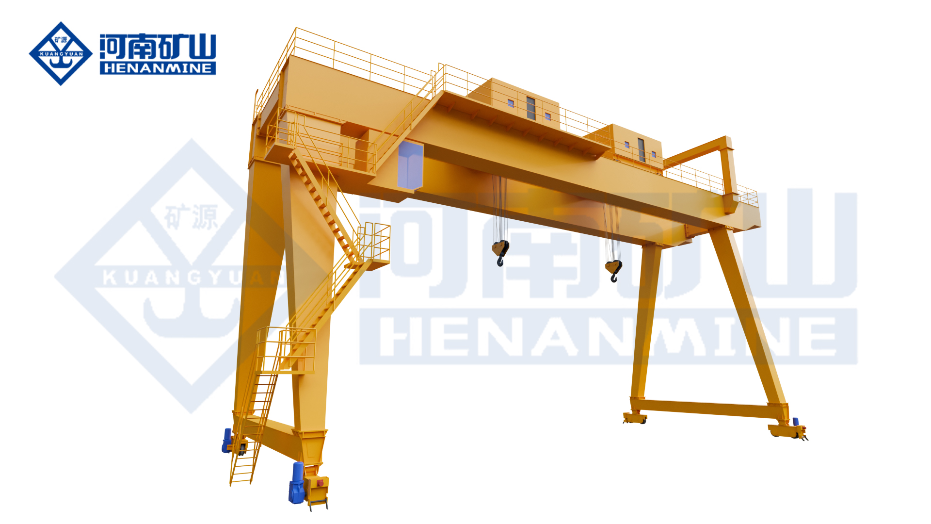
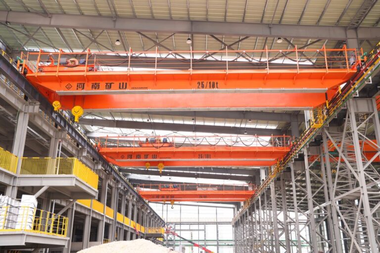
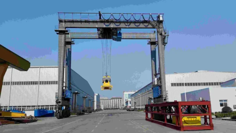
Henan Mine Crane mb1 double-girder semi-gantry crane showing the primary gantry structure and electric-hoist lifting arrangement.
The MB₁ double-main-girder electric hoist semi-gantry crane combines a compact double-girder lifting structure with a semi-gantry runway arrangement. The source lists A3–A5 working class.
The source specifically highlights low overall height and compact dimensions for low workshops and narrow passages. Buyers should provide the full building section because the elevated runway, wall clearance, ground rail and hook approach must work together.
Quick Specifications
| Product Model |
MB₁ |
| Type-Test Product Name |
Electric Hoist Gantry Crane |
| Lifting Mechanism |
Electric hoist |
| Lifting Capacity |
Configured according to project requirements |
| Span |
Configured according to rail / runway center distance |
| Lifting Height |
Configured according to site and process requirements |
| Working Duty |
Source-defined where stated; otherwise project-specific |
| Cantilever |
Optional where source-supported and required by the process |
| Control Method |
Configured according to source-supported options and project requirements |
Best For: For low buildings or narrow production aisles where one side of the crane can run on an elevated building runway and the other on a ground rail.
Request A MB1 Double-Girder Semi-Gantry Crane Quote
Product Overview
Double-main-girder electric-hoist semi-gantry crane.
Source working class A3–A5.
Source highlights compact structure, low overall crane height and smaller external dimensions.
Any capacity, span, speed, wheel load, energy saving, duty or other guaranteed value that is not explicitly published on the source page should be engineered from the actual project and written into the technical agreement rather than assumed from a similar crane.
Why Choose MB1 Double-Girder Semi-Gantry Crane?
Low Overall Height
Useful when building clearance is the main project constraint.
Narrow-Space Fit
Compact external dimensions suit restricted production passages.
Double-Girder Structure
Provides a stable crane platform within the semi-gantry layout.
Three-in-One Drives
Integrated travel drives reduce mechanical complexity.
Multiple Control Modes
Cab, pendant, wireless and PLC-linked operation can be selected.
Product Images

Official source image associated with the MB1 Double-Girder Semi-Gantry Crane, showing the semi-gantry structure, runway interface or industrial installation.
|

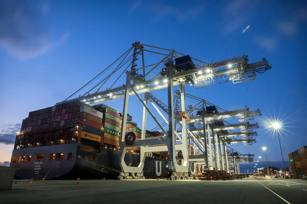
Official source image associated with the MB1 Double-Girder Semi-Gantry Crane, showing the semi-gantry structure, runway interface or industrial installation.
|

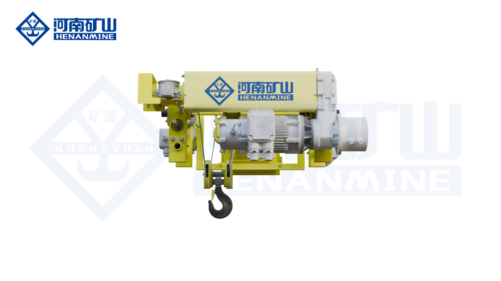
Official source image associated with the MB1 Double-Girder Semi-Gantry Crane, showing the semi-gantry structure, runway interface or industrial installation.
|

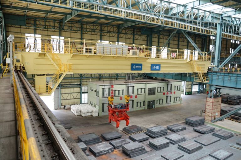
Official source image associated with the MB1 Double-Girder Semi-Gantry Crane, showing the semi-gantry structure, runway interface or industrial installation.
|

Official source image associated with the MB1 Double-Girder Semi-Gantry Crane, showing the semi-gantry structure, runway interface or industrial installation.
|

Official source image associated with the MB1 Double-Girder Semi-Gantry Crane, showing the semi-gantry structure, runway interface or industrial installation.
|
Main Crane Components
| Main Girder / Bridge |
Selected from the product structure, span, load, duty and site environment. |
| Gantry Legs / Semi-Gantry Support |
Ground-supported or building-integrated according to the specific model. |
| Electric Hoist / Hoist Trolley |
Provides lifting and cross travel; arrangement depends on the product configuration. |
| Gantry Travel System |
Moves the crane along the ground rail or combined semi-gantry runway. |
| Cantilever / End Structure |
Configured only where outside-span hook coverage is required. |
| Electrical & Control System |
Configured for source-supported control modes, site power and project safety requirements. |
Technical Parameters
| Model |
MB₁ |
| Product Type |
MB1 Double-Main-Girder Electric Hoist Semi-Gantry Crane |
| Type-Test Product Name |
Electric Hoist Gantry Crane |
| Capacity |
Project-specific |
| Span |
Project-specific |
| Lifting Height |
Project-specific |
| Runway / Travel Length |
Project-specific |
| Hoisting Speed |
Project-specific unless source-stated in a special section |
| Cross / Gantry Travel Speed |
Project-specific |
| Working Duty |
Project-specific unless source-stated |
| Cantilever |
Project-specific where applicable |
| Control Method |
Project-specific |
| Power Supply |
According to site electrical conditions |
| Outdoor Protection |
According to wind, rain, dust, temperature and corrosion conditions |
Source-Confirmed Features & Buyer-Defined Options
Source-confirmed product facts:
- Double-main-girder electric-hoist semi-gantry crane.
- Source working class A3–A5.
- Source highlights compact structure, low overall crane height and smaller external dimensions.
- Intended for flexible work in low buildings and narrow passages according to source.
- Bridge and trolley travel use three-in-one direct-drive mechanisms.
- Cab, pendant, wireless remote and PLC linked control are source-listed.
- Pendant / wireless operation is also repeated by the source as a flexible operating option.
Buyer-defined items:
- Maximum suspended load including rigging / attachment
- Span, lifting height and travel length
- Cantilever / outside-span coverage if required
- Ground rail, foundation or elevated semi-gantry runway
- Operating frequency and working duty
- Indoor / outdoor environmental conditions
- Control method and safety functions
- Installation, load testing and commissioning scope
Application Scenarios
| Low Workshops |
Lifting where overall crane height is constrained. |
| Sidewall Production Bays |
One elevated runway integrated with the building. |
| Narrow Industrial Passages |
Compact semi-gantry coverage. |
| Manufacturing / Assembly |
General A3–A5 handling near production lines. |
How to Select the Right MB1 Double-Girder Semi-Gantry Crane
1. Provide the Building Cross-Section
Include roof, wall, elevated runway and floor rail elevations.
2. Define Hook Approach
Measure how close the hook must reach to the wall / equipment.
3. Verify Both Runways
Building-side and ground-side structural capacities must be checked.
4. Confirm A3–A5 Duty
Use real load spectrum and cycles.
5. Select Control Mode
Choose cab, pendant, wireless or PLC integration around visibility and process.
Semi-Gantry Building Interface
| Elevated Runway |
Provide beam / column capacity and rail elevation. |
| Ground Rail |
Provide foundation and rail information on the opposite side. |
| Overall Height |
Source highlights compact geometry; final crane must be checked against actual roof clearance. |
| Narrow Passage |
Check gantry leg, end carriage and load envelope against equipment and traffic routes. |
Safety & Control: What Buyers Should Confirm
• Rated capacity, overload protection and below-the-hook attachment weight
• Upper / lower hoisting limits and gantry / trolley travel limits
• Brake and emergency-stop requirements
• Rail-end stops, buffers and anti-collision requirements
• Outdoor wind protection / anchoring or rail clamps where required
• Operator visibility and control method
• Attachment changeover interlocks where grab / electromagnetic equipment is used
• Factory and site load / functional acceptance tests
Installation & Maintenance
Before manufacture and installation, confirm rail center distance, runway length, rail elevation, foundation or building-runway capacity, available lifting height, cantilever clearance, power supply and erection access. Outdoor projects should also define wind, rain, dust and temperature conditions.
Maintenance should follow the supplied crane manual and actual duty. Routine work should cover the electric hoist, ropes, hooks / attachments, brakes, wheels, three-in-one drives where fitted, rail alignment, fasteners, limits and electrical protection. Semi-gantry cranes also require coordinated inspection of both the elevated runway and ground rail.
What Information Do We Need for a Quote?
| 1 |
Maximum load |
| 2 |
Span |
| 3 |
Lifting height |
| 4 |
Travel length |
| 5 |
Building/elevated runway drawing |
| 6 |
Ground rail / foundation data |
| 7 |
Overall-height limit |
| 8 |
Wall / equipment clearances |
| 9 |
A3–A5 duty inputs |
| 10 |
Control mode |
| 11 |
Power supply |
| 12 |
Destination / installation scope |
Frequently Asked Questions
How do I choose between a full gantry and a semi-gantry crane?
Use a full gantry when both sides should be ground-supported. A semi-gantry is relevant when one side can safely use an elevated building runway and the site benefits from a smaller floor footprint.
Should I add a cantilever?
Only when the hook must reach outside the clear span, such as a truck loading or storage position. Cantilever length changes structural reactions and should be defined from the site layout.
Are capacity and span fixed for these products?
Unless the source page explicitly publishes a value, capacity, span and lifting height should be engineered from the actual project.
What site information is most important?
A plan and cross-section showing rails, foundations or elevated runway, building / equipment clearances, loading positions and travel length will significantly improve quotation accuracy.
Can the crane be used outdoors?
Many gantry applications are outdoors, but wind, rain, temperature, corrosion and anchoring requirements must be specified for the actual site.
Related Electric Hoist Gantry Cranes
MH Electric Hoist Gantry Crane
MHZE Grab & Hook Dual-Purpose Electric Hoist Gantry Crane
MHL L-Type Electric Hoist Gantry Crane
MHH Truss Electric Hoist Gantry Crane
KSMH New-Type Electric Hoist Gantry Crane
KSMB New-Type Electric Hoist Semi-Gantry Crane
Request A MB1 Double-Girder Semi-Gantry Crane Quote
Send your load, span, lifting height, travel length, site layout, rail / foundation or building-runway data, operating cycle and control requirements. Henan Mine Crane engineers can then review the correct gantry structure and prepare a project-specific configuration and quotation.
Request A Quote | View Gantry Cranes